DTC P0AA6-49: Hybrid/EV Battery Voltage System Isolation Internal Electronic Failure; DTC P1C7C-49: Hybrid/EV Battery Voltage System Isolation (A/C Area) Internal Electronic Failure; DTC P1C7D-49: Hybrid/EV Battery Voltage System Isolation (Hybrid/EV Battery Area) Internal Electronic Failure; DTC P1C7E-49: Hybrid/EV Battery Voltage System Isolation (Transaxle Area) Internal Electronic Failure; DTC P1C7F-49: Hybrid/EV Battery Voltage System Isolation (Direct Current Area) Internal Electronic Failure; DTC P1C80-49: Hybrid/EV Battery Voltage System Isolation (Rear Motor Area) Internal Electronic Failure [12/2019 - 11/2023]: Procedure
- CHECK DTC OUTPUT (HYBRID CONTROL)
- Check for DTCs.
Powertrain > Hybrid Control > Trouble Codes
Result
Result Proceed to P0AA6-49, P1C7C-49, P1C7D-49, P1C7E-49, P1C7F-49 or P1C80-49 only is output, or DTCs except the ones in the table below are also output. A Any of the following DTCs are also output. B Malfunction Content Relevant DTC Microcomputer malfunction P0606-47 Hybrid/EV Powertrain Control Module Processor Watchdog / Safety MCU Failure P0606-87 Hybrid/EV Powertrain Control Module Processor to Monitoring Processor Missing Message P060A-29 Hybrid/EV Powertrain Control Module Monitoring Processor Signal Invalid P060A-44 Hybrid/EV Powertrain Control Module Monitoring Processor Data Memory Failure P060A-45 Hybrid/EV Powertrain Control Module Monitoring Processor Program Memory Failure P060A-47 Hybrid/EV Powertrain Control Module Monitoring Processor Watchdog / Safety MCU Failure P060A-49 Hybrid/EV Powertrain Control Module Monitoring Processor Internal Electronic Failure P060A-87 Hybrid/EV Powertrain Control Module Processor from Monitoring Processor Missing Message P060B-1C Hybrid/EV Powertrain Control Module A/D Processing Voltage Out of Range P060B-49 Hybrid/EV Powertrain Control Module A/D Processing Internal Electronic Failure P060B-71 Hybrid/EV Powertrain Control Module A/D Processing Actuator Stuck P1CE3-1C Hybrid/EV Powertrain Control Module Monitoring Processor A/D Processing Voltage Out of Range P1CE3-49 Hybrid/EV Powertrain Control Module Monitoring Processor A/D Processing Internal Electronic Failure P1CE3-71 Hybrid/EV Powertrain Control Module Monitoring Processor A/D Processing Actuator Stuck P0AFC-96 Hybrid/EV Battery Sensor Module Component Internal Failure P0AFC-00 Hybrid/EV Battery Sensor Module P0AFC-49 Hybrid/EV Battery Sensor Module Internal Electronic Failure P0AFC-62 Hybrid/EV Battery Sensor Module Signal Compare Failure Power Source Circuit Malfunction P0688-1F ECM/PCM Power Relay Sense Circuit Intermittent P0AFC-16 Hybrid/EV Battery Sensor Module Circuit Voltage Below Threshold System malfunction P1C9E-9F Hybrid/EV System Reset Stuck Off HINT:
- P0AA6-49, P1C7C-49, P1C7D-49, P1C7E-49, P1C7F-49 or P1C80-49 may be output as a result of the malfunction indicated by the DTCs above.
- The chart above is listed in inspection order of priority.
- Check DTCs that are output at the same time by following the listed order. (The main cause of the malfunction can be determined without performing unnecessary inspections.)
- P0AA6-49, P1C7C-49, P1C7D-49, P1C7E-49, P1C7F-49 or P1C80-49 may be output as a result of the malfunction indicated by the DTCs above.
- Turn the ignition switch off.
Result:
B
GO TO DTC CHART (HYBRID CONTROL SYSTEM)
Refer to DIAGNOSTIC TROUBLE CODE CHART [12/2019 - 09/2020] , or refer to DIAGNOSTIC TROUBLE CODE CHART [09/2020 - 10/2021] , or refer to DIAGNOSTIC TROUBLE CODE CHART [10/2021 - 11/2023]
Result:
A
See step 2
- Check for DTCs.
- CHECK DTC OUTPUT (HYBRID CONTROL)
- Check for DTCs.
Powertrain > Hybrid Control > Trouble Codes
NOTE:- DTC P1C7C-49, P1C7D-49, P1C7E-49, P1C7F-49 and P1C80-49 are not stored with P0AA6-49 at the same time. If a drop in insulation resistance is detected and DTC P0AA6-49 is output, wait for 1 minute with the ignition switch ON (READY), the shift lever in D and the air conditioning system on within the same trip, then turn the ignition switch off and wait for 2 minutes to determine the DTC (P1C7C-49, P1C7D-49, P1C7E-49, P1C7F-49 or P1C80-49).
- If only DTC P0AA6-49 is output, perform the diagnostic procedure for DTC P0AA6-49 to inspect all of the high voltage circuits.
- When any other DTC indicating parts which the insulation resistance dropped are output, perform the diagnostic procedure for each DTC.
Result
Result Proceed to P0AA6-49 (decrease in the insulation resistance of the high-voltage circuit) only is output. A P0AA6-49 and P1C7C-49 (decrease in the insulation resistance of the air conditioning system area) are output. B P0AA6-49 and P1C7D-49 (decrease in the insulation resistance of the HV battery area) are output. C P0AA6-49 and P1C7E-49 (decrease in the insulation resistance of the hybrid vehicle transaxle assembly area) are output. D P0AA6-49 and P1C7F-49 (decrease in the insulation resistance of the high-voltage direct current area) are output. E P0AA6-49 and P1C80-49 (decrease in the insulation resistance of the rear motor area) are output. F - Turn the ignition switch off.
Result:
B
See step 12
Result:
C
See step 13
Result:
D
See step 21
Result:
E
See step 26
Result:
F
See step 38
Result:
A
See step 3
- Check for DTCs.
- CHECK HYBRID VEHICLE TRANSAXLE ASSEMBLY (MOTOR CABLE (FOR MG2)) WARNING:
Be sure to wear insulated gloves.
- Check that the service plug grip is not installed.NOTE:
After removing the service plug grip, do not turn the ignition switch to ON (READY), unless instructed by the repair information because this may cause a malfunction.
- Disconnect the motor cable from the inverter with converter assembly.
HINT:
Make sure that no foreign matter, coolant or water enters the inverter with converter assembly.
- Connect the cable to the negative (-) auxiliary battery terminal.
- Turn the ignition switch to ON.NOTE:
Turning the ignition switch to ON with the service plug grip removed causes DTCs to be stored. Clear the DTCs after performing this inspection.
- Move the shift lever to N and lift the vehicle.
- Turn the ignition switch off.
- Using a megohmmeter set to 500 V, measure the resistance according to the value(s) in the table below while rotating the front wheels 2 revolutions in the same direction simultaneously.NOTE:
- Carefully perform this inspection as the motor (MG2) may generate current when the front wheels are rotated by hand.
- Be sure to set the megohmmeter to 500 V when performing this test. Using a setting higher than 500 V can result in damage to the component being inspected.
HINT:
As the insulation resistance may vary when motor (MG2) rotates, perform this inspection while rotating the front wheels.
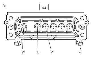
Standard Resistance
Tester Connection Condition Specified Condition w2-2 (U) - Body ground and shield ground Ignition switch off 100 MΩ or higher w2-3 (V) - Body ground and shield ground Ignition switch off 100 MΩ or higher w2-1 (W) - Body ground and shield ground Ignition switch off 100 MΩ or higher *1 Shield Ground *a Motor Cable (for MG2)
(Inverter with Converter Assembly Side) - Lower the vehicle and move the shift lever to P.
- Disconnect the cable from the negative (-) auxiliary battery terminal.
Result
Proceed to OK NG
Result:
NG
See step 9
Result:
OK
See step 4
- Check that the service plug grip is not installed.
- CHECK HYBRID VEHICLE TRANSAXLE ASSEMBLY (MOTOR CABLE (FOR MG1)) WARNING:
Be sure to wear insulated gloves.
- Check that the service plug grip is not installed.NOTE:
After removing the service plug grip, do not turn the ignition switch to ON (READY), unless instructed by the repair information because this may cause a malfunction.
- Connect the cable to the negative (-) auxiliary battery terminal.
- Turn the ignition switch to ON.NOTE:
Turning the ignition switch to ON with the service plug grip removed causes DTCs to be stored. Clear the DTCs after performing this inspection.
- Move the shift lever to N and lift the vehicle.
- Turn the ignition switch off.
- Using a megohmmeter set to 500 V, measure the resistance according to the value(s) in the table below while rotating the front wheels 2 revolutions in the same direction simultaneously.NOTE:
- Carefully perform this inspection as the generator (MG1) may generate current when the front wheels are rotated by hand.
- Be sure to set the megohmmeter to 500 V when performing this test. Using a setting higher than 500 V can result in damage to the component being inspected.
HINT:
As the insulation resistance may vary when generator (MG1) rotates, perform this inspection while rotating the front wheels.
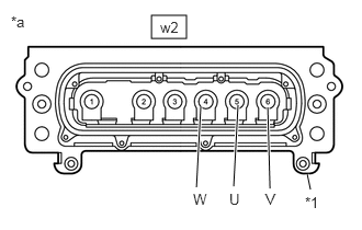
Standard Resistance
Tester Connection Condition Specified Condition w2-5 (U) - Body ground and shield ground Ignition switch off 100 MΩ or higher w2-6 (V) - Body ground and shield ground Ignition switch off 100 MΩ or higher w2-4 (W) - Body ground and shield ground Ignition switch off 100 MΩ or higher *1 Shield Ground *a Motor Cable (for MG1)
(Inverter with Converter Assembly Side) - Lower the vehicle and move the shift lever to P.
- Disconnect the cable from the negative (-) auxiliary battery terminal.
Result
Proceed to OK NG
Result:
NG
See step 10
Result:
OK
See step 5
- Check that the service plug grip is not installed.
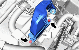
- CHECK REAR TRACTION MOTOR WITH TRANSAXLE ASSEMBLY (HV FLOOR UNDER WIRE (REAR TRACTION MOTOR CABLE)) WARNING:
Be sure to wear insulated gloves.
- Check that the service plug grip is not installed.NOTE:
After removing the service plug grip, do not turn the ignition switch to ON (READY), unless instructed by the repair information because this may cause a malfunction.
- Disconnect the HV floor under wire (rear traction motor cable) from the inverter with converter assembly.
HINT:
Make sure that no foreign matter, coolant or water enters the inverter with converter assembly.
- Connect the cable to the negative (-) auxiliary battery terminal.
- Turn the ignition switch to ON.NOTE:
Turning the ignition switch to ON with the service plug grip removed causes DTCs to be stored. Clear the DTCs after performing this inspection.
- Move the shift lever to N and lift the vehicle.
- Turn the ignition switch off.
- Using a megohmmeter set to 500 V, measure the resistance according to the value(s) in the table below while rotating the rear wheels 2 revolutions in the same direction simultaneously.NOTE:
- Carefully perform this inspection as the rear motor (MGR) may generate current when the rear wheels are rotated by hand.
- Be sure to set the megohmmeter to 500 V when performing this test. Using a setting higher than 500 V can result in damage to the component being inspected.
HINT:
As the insulation resistance may vary when rear motor (MGR) rotates, perform this inspection while rotating the rear wheels.
Standard Resistance
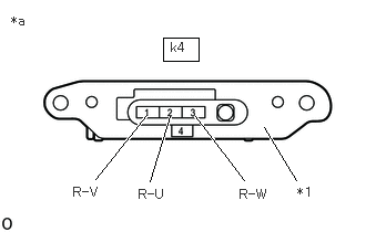
Tester Connection Condition Specified Condition k4-2 (R-U) - Body ground and shield ground Ignition switch off 100 MΩ or higher k4-1 (R-V) - Body ground and shield ground Ignition switch off 100 MΩ or higher k4-3 (R-W) - Body ground and shield ground Ignition switch off 100 MΩ or higher *1 Shield Ground *a HV Floor Under Wire (Rear Traction Motor Cable)
(Inverter with Converter Assembly Side) - Lower the vehicle and move the shift lever to P.
- Disconnect the cable from the negative (-) auxiliary battery terminal.
Result
Proceed to OK NG
Result:
NG
See step 11
Result:
OK
See step 6
- Check that the service plug grip is not installed.
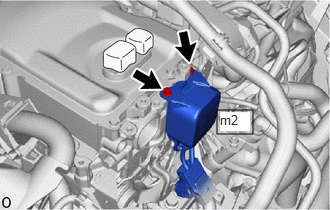
- CHECK HV AIR CONDITIONING WIRE WARNING:
Be sure to wear insulated gloves.
- Check that the service plug grip is not installed.NOTE:
After removing the service plug grip, do not turn the ignition switch to ON (READY), unless instructed by the repair information because this may cause a malfunction.
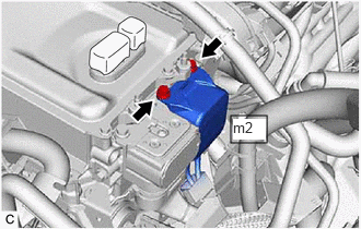
- Disconnect the HV air conditioning wire connector from the inverter with converter assembly.
HINT:
Make sure that no foreign matter has entered or contaminated the HV air conditioning wire.
- Using a megohmmeter set to 500 V, measure the resistance according to the value(s) in the table below.NOTE:
- Be sure to set the megohmmeter to 500 V when performing this test. Using a setting higher than 500 V can result in damage to the component being inspected.
- Be sure to inspect with connecting the tester probes to the tips of the terminal.
Standard Resistance
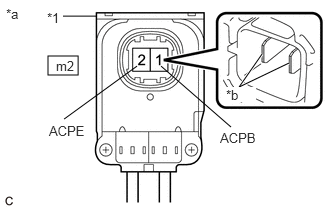
Tester Connection Condition Specified Condition m2-1 (ACPB) - Body ground and shield ground Ignition switch off 3 MΩ or higher m2-2 (ACPE) - Body ground and shield ground Ignition switch off 3 MΩ or higher *1 Shield Ground *a HV Air Conditioning Wire
(Inverter with Converter Assembly Side)*b Tip of Terminal Result
Proceed to OK NG
Result:
NG
See step 28
Result:
OK
See step 7
- Check that the service plug grip is not installed.
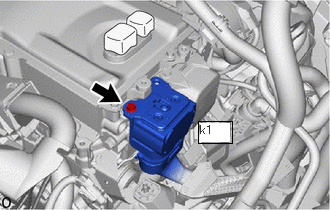
- CHECK FLOOR UNDER WIRE WARNING:
Be sure to wear insulated gloves.
- Check that the service plug grip is not installed.NOTE:
After removing the service plug grip, do not turn the ignition switch to ON (READY), unless instructed by the repair information because this may cause a malfunction.
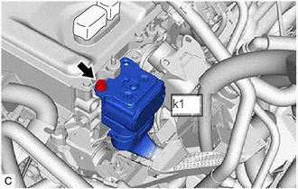
- Disconnect the HV floor under wire connector from the inverter with converter assembly.
HINT:
Make sure that no foreign matter has entered or contaminated the HV floor under wire.
- Using a megohmmeter set to 500 V, measure the resistance according to the value(s) in the table below.NOTE:
- Be sure to set the megohmmeter to 500 V when performing this test. Using a setting higher than 500 V can result in damage to the component being inspected.
- Be sure not to damage or deform the terminal being inspected.
Standard Resistance
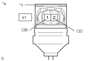
Tester Connection Condition Specified Condition k1-1 (CBI) - Body ground and shield ground Ignition switch off 10 MΩ or higher k1-2 (CEI) - Body ground and shield ground Ignition switch off 10 MΩ or higher HINT:
Visually inspect the HV floor under wire for damage. If there is any damage, then this is the likely cause of low insulation resistance.
*1 Shield Ground *a HV Floor Under Wire
(Inverter with Converter Assembly Side)Result
Proceed to OK NG
Result:
NG
See step 31
Result:
OK
See step 8
- Check that the service plug grip is not installed.
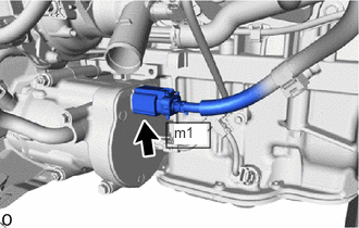
- CHECK INVERTER WITH CONVERTER ASSEMBLY WARNING:
Be sure to wear insulated gloves.
- Check that the service plug grip is not installed.NOTE:
After removing the service plug grip, do not turn the ignition switch to ON (READY), unless instructed by the repair information because this may cause a malfunction.
- Connect the HV floor under wire connector to the inverter with converter assembly.
- Using a megohmmeter set to 500 V, measure the resistance according to the value(s) in the table below.NOTE:
Be sure to set the megohmmeter to 500 V when performing this test. Using a setting higher than 500 V can result in damage to the component being inspected.
Standard Resistance
Tester Connection Condition Specified Condition High voltage terminal - Body ground Ignition switch off 1 MΩ or higher HINT:
Perform this inspection with the motor cable, HV floor under wire (rear traction motor cable) and HV air conditioning wire disconnected from the inverter with converter assembly.
*a High Voltage Terminal Result
Proceed to OK NG
Result:
OK
See step 13
Result:
NG
See step 42
- Check that the service plug grip is not installed.
- CHECK MOTOR CABLE (FOR MG2) WARNING:
Be sure to wear insulated gloves.
- Check that the service plug grip is not installed.NOTE:
After removing the service plug grip, do not turn the ignition switch to ON (READY), unless instructed by the repair information because this may cause a malfunction.
- Remove the motor cable from the hybrid vehicle transaxle assembly.
Refer to REMOVAL [12/2019 - 10/2022] , or refer to REMOVAL [10/2022 - 11/2023]
- Using a megohmmeter set to 500 V, measure the resistance according to the value(s) in the table below.NOTE:
Be sure to set the megohmmeter to 500 V when performing this test. Using a setting higher than 500 V can result in damage to the component being inspected.
Standard Resistance
Tester Connection Condition Specified Condition w2-2 (U) - Shield ground Ignition switch off 100 MΩ or higher w2-3 (V) - Shield ground Ignition switch off 100 MΩ or higher w2-1 (W) - Shield ground Ignition switch off 100 MΩ or higher *1 Shield Ground *a Motor Cable (for MG2)
(Inverter with Converter Assembly Side)Result
Proceed to OK NG
Result:
OK
See step 24
Result:
NG
See step 25
- Check that the service plug grip is not installed.
- CHECK MOTOR CABLE (FOR MG1) WARNING:
Be sure to wear insulated gloves.
- Check that the service plug grip is not installed.NOTE:
After removing the service plug grip, do not turn the ignition switch to ON (READY), unless instructed by the repair information because this may cause a malfunction.
- Remove the motor cable from the hybrid vehicle transaxle assembly.
Refer to REMOVAL [12/2019 - 10/2022] , or refer to REMOVAL [10/2022 - 11/2023]
- Using a megohmmeter set to 500 V, measure the resistance according to the value(s) in the table below.NOTE:
Be sure to set the megohmmeter to 500 V when performing this test. Using a setting higher than 500 V can result in damage to the component being inspected.
Standard Resistance
Tester Connection Condition Specified Condition w2-5 (U) - Shield ground Ignition switch off 100 MΩ or higher w2-6 (V) - Shield ground Ignition switch off 100 MΩ or higher w2-4 (W) - Shield ground Ignition switch off 100 MΩ or higher *1 Shield Ground *a Motor Cable (for MG1)
(Inverter with Converter Assembly Side)Result
Proceed to OK NG
Result:
OK
See step 24
Result:
NG
See step 25
- Check that the service plug grip is not installed.
- CHECK FLOOR UNDER WIRE (REAR TRACTION MOTOR CABLE) WARNING:
Be sure to wear insulated gloves.
- Check that the service plug grip is not installed.NOTE:
After removing the service plug grip, do not turn the ignition switch to ON (READY), unless instructed by the repair information because this may cause a malfunction.
- Remove the HV floor under wire (rear traction motor cable) from the rear traction motor with transaxle assembly.
Refer to REMOVAL [12/2019 - 10/2022] , or refer to REMOVAL [10/2022 - 11/2023]
- Using a megohmmeter set to 500 V, measure the resistance according to the value(s) in the table below.NOTE:
Be sure to set the megohmmeter to 500 V when performing this test. Using a setting higher than 500 V can result in damage to the component being inspected.
Standard Resistance
Tester Connection Condition Specified Condition k4-2 (R-U) - Shield ground Ignition switch off 100 MΩ or higher k4-1 (R-V) - Shield ground Ignition switch off 100 MΩ or higher k4-3 (R-W) - Shield ground Ignition switch off 100 MΩ or higher *1 Shield Ground *a HV Floor Under Wire (Rear Traction Motor Cable)
(Inverter with Converter Assembly Side)Result
Proceed to OK NG
Result:
OK
See step 41
Result:
NG
See step 44
- Check that the service plug grip is not installed.
- GO TO AIR CONDITIONING SYSTEM (P1C7C-49)
Result
Proceed to NEXT Result:
NEXT
PERFORM CONFIRMATION AFTER REPLACING PARTS
Refer to CONFIRMATION DRIVING PATTERN
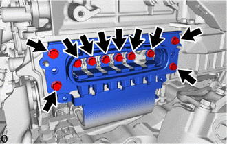
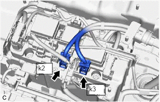
- CHECK HV BATTERY JUNCTION BLOCK ASSEMBLY WARNING:
Be sure to wear insulated gloves.
HINT:
Make sure that no foreign matter or water has entered the HV battery.
- Check that the service plug grip is not installed.NOTE:
After removing the service plug grip, do not turn the ignition switch to ON (READY), unless instructed by the repair information because this may cause a malfunction.
- Remove the No. 10 HV battery shield panel.
Refer to REMOVAL [12/2019 - 10/2022] , or refer to REMOVAL [10/2022 - 11/2023]
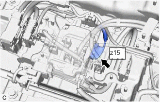
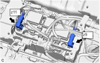
- Disconnect the z15 battery voltage sensor connector.NOTE:
Insulate each disconnected high-voltage connector with insulating tape. Wrap the connector from the wire harness side to the end of the connector.
- Disconnect the high voltage cable connectors of the HV battery from the HV battery junction block assembly.NOTE:
Insulate each disconnected high-voltage connector with insulating tape. Wrap the connector from the wire harness side to the end of the connector.
- Using a megohmmeter set to 500 V, measure the resistance according to the value(s) in the table below.NOTE:
Be sure to set the megohmmeter to 500 V when performing this test. Using a setting higher than 500 V can result in damage to the component being inspected.
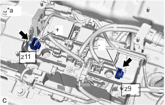
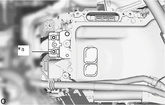
Standard Resistance
Tester Connection Condition Specified Condition z11-1 (+) - Body ground Ignition switch off 10 MΩ or higher z9-1 (-) - Body ground Ignition switch off 10 MΩ or higher *a Component without harness connected
(HV Battery Junction Block Assembly)Result
Proceed to OK NG
Result:
NG
See step 33
Result:
OK
See step 14
- Check that the service plug grip is not installed.
- CHECK HV BATTERY (HIGH VOLTAGE CABLE) WARNING:
Be sure to wear insulated gloves.
- Check that the service plug grip is not installed.NOTE:
After removing the service plug grip, do not turn the ignition switch to ON (READY), unless instructed by the repair information because this may cause a malfunction.
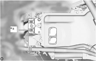
- Using a megohmmeter set to 500 V, measure the resistance according to the value(s) in the table below.NOTE:
Be sure to set the megohmmeter to 500 V when performing this test. Using a setting higher than 500 V can result in damage to the component being inspected.
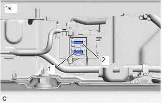
Standard Resistance
Tester Connection Condition Specified Condition 2 - Body ground Ignition switch off 10 MΩ or higher *a Service Plug Grip Removed
(Service Plug Grip Connecting Terminals)Result
Proceed to OK NG
Result:
NG
See step 20
Result:
OK
See step 15
- Check that the service plug grip is not installed.
- CHECK HV BATTERY WARNING:
Be sure to wear insulated gloves.
- Check that the service plug grip is not installed.NOTE:
After removing the service plug grip, do not turn the ignition switch to ON (READY), unless instructed by the repair information because this may cause a malfunction.
- Using a megohmmeter set to 500 V, measure the resistance according to the value(s) in the table below.NOTE:
Be sure to set the megohmmeter to 500 V when performing this test. Using a setting higher than 500 V can result in damage to the component being inspected.
Standard Resistance
Tester Connection Condition Specified Condition 1 - Body ground Ignition switch off 10 MΩ or higher *a Service Plug Grip Removed
(Service Plug Grip Connecting Terminals)Result
Proceed to OK NG
Result:
NG
See step 17
Result:
OK
See step 16
- Check that the service plug grip is not installed.
- REPLACE BATTERY VOLTAGE SENSOR
Refer to REMOVAL [12/2019 - 10/2022] , or refer to REMOVAL [10/2022 - 11/2023]
Result
Proceed to NEXT Result:
NEXT
PERFORM CONFIRMATION AFTER REPLACING PARTS
Refer to CONFIRMATION DRIVING PATTERN
- CHECK HV BATTERY (HIGH VOLTAGE CABLE) WARNING:
Be sure to wear insulated gloves and protective goggles.
- Check that the service plug grip is not installed.NOTE:
After removing the service plug grip, do not turn the ignition switch to ON (READY), unless instructed by the repair information because this may cause a malfunction.
- Remove the No. 1 hybrid battery shield sub-assembly.
Refer to REMOVAL [12/2019 - 10/2022] , or refer to REMOVAL [10/2022 - 11/2023]
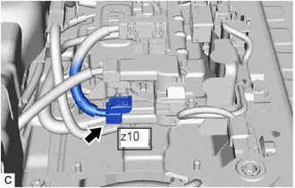
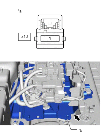
- Disconnect the high voltage connector.NOTE:
Insulate each disconnected high-voltage connector with insulating tape. Wrap the connector from the wire harness side to the end of the connector.
- Using a megohmmeter set to 500 V, measure the resistance according to the value(s) in the table below.NOTE:
Be sure to set the megohmmeter to 500 V when performing this test. Using a setting higher than 500 V can result in damage to the component being inspected.
Standard Resistance
Tester Connection Condition Specified Condition z10-1 - HV battery carrier Ignition switch off 10 MΩ or higher *a High Voltage Cable
(Hybrid Battery Terminal Block Side)*b HV Battery Carrier Result
Proceed to OK NG
Result:
NG
See step 20
Result:
OK
See step 18
- Check that the service plug grip is not installed.
- CHECK HV BATTERY (HIGH VOLTAGE CABLE) WARNING:
Be sure to wear insulated gloves and protective goggles.
- Check that the service plug grip is not installed.NOTE:
After removing the service plug grip, do not turn the ignition switch to ON (READY), unless instructed by the repair information because this may cause a malfunction.
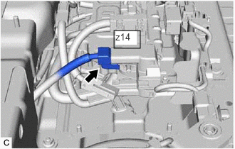
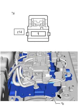
- Disconnect the high voltage connector.NOTE:
Insulate each disconnected high-voltage connector with insulating tape. Wrap the connector from the wire harness side to the end of the connector.
- Using a megohmmeter set to 500 V, measure the resistance according to the value(s) in the table below.NOTE:
Be sure to set the megohmmeter to 500 V when performing this test. Using a setting higher than 500 V can result in damage to the component being inspected.
Standard Resistance
Tester Connection Condition Specified Condition z14-1 - HV battery carrier Ignition switch off 10 MΩ or higher *a High Voltage Cable
(Hybrid Battery Terminal Block Side)*b HV Battery Carrier Result
Proceed to OK NG
Result:
NG
See step 20
Result:
OK
See step 19
- Check that the service plug grip is not installed.
- REPLACE HYBRID BATTERY TERMINAL BLOCK
Refer to REMOVAL [12/2019 - 10/2022] , or refer to REMOVAL [10/2022 - 11/2023]
Result
Proceed to NEXT Result:
NEXT
PERFORM CONFIRMATION AFTER REPLACING PARTS
Refer to CONFIRMATION DRIVING PATTERN
- REPLACE HV BATTERY
Refer to REMOVAL [12/2019 - 10/2022] , or refer to REMOVAL [10/2022 - 11/2023]
Result
Proceed to NEXT Result:
NEXT
PERFORM CONFIRMATION AFTER REPLACING PARTS
Refer to CONFIRMATION DRIVING PATTERN
- CHECK INVERTER WITH CONVERTER ASSEMBLY WARNING:
Be sure to wear insulated gloves.
- Check that the service plug grip is not installed.NOTE:
After removing the service plug grip, do not turn the ignition switch to ON (READY), unless instructed by the repair information because this may cause a malfunction.
- Disconnect the motor cable from the inverter with converter assembly.
HINT:
Make sure that no foreign matter, coolant or water enters the inverter with converter assembly.
- Using a megohmmeter set to 500 V, measure the resistance according to the value(s) in the table below.NOTE:
Be sure to set the megohmmeter to 500 V when performing this test. Using a setting higher than 500 V can result in damage to the component being inspected.
Standard Resistance
Tester Connection Condition Specified Condition High voltage terminal - Body ground Ignition switch off 1 MΩ or higher HINT:
Perform this inspection with the motor cable disconnected from the inverter with converter assembly.
*a High Voltage Terminal Result
Proceed to OK NG
Result:
NG
See step 42
Result:
OK
See step 22
- Check that the service plug grip is not installed.
- CHECK MOTOR CABLE (FOR MG2) WARNING:
Be sure to wear insulated gloves.
- Check that the service plug grip is not installed.NOTE:
After removing the service plug grip, do not turn the ignition switch to ON (READY), unless instructed by the repair information because this may cause a malfunction.
- Remove the motor cable from the hybrid vehicle transaxle assembly.
Refer to REMOVAL [12/2019 - 10/2022] , or refer to REMOVAL [10/2022 - 11/2023]
- Using a megohmmeter set to 500 V, measure the resistance according to the value(s) in the table below.NOTE:
Be sure to set the megohmmeter to 500 V when performing this test. Using a setting higher than 500 V can result in damage to the component being inspected.
Standard Resistance
Tester Connection Condition Specified Condition w2-2 (U) - Shield ground Ignition switch off 100 MΩ or higher w2-3 (V) - Shield ground Ignition switch off 100 MΩ or higher w2-1 (W) - Shield ground Ignition switch off 100 MΩ or higher *1 Shield Ground *a Motor Cable (for MG2)
(Inverter with Converter Assembly Side)Result
Proceed to OK NG
Result:
NG
See step 25
Result:
OK
See step 23
- Check that the service plug grip is not installed.
- CHECK MOTOR CABLE (FOR MG1) WARNING:
Be sure to wear insulated gloves.
- Check that the service plug grip is not installed.NOTE:
After removing the service plug grip, do not turn the ignition switch to ON (READY), unless instructed by the repair information because this may cause a malfunction.
- Remove the motor cable from the hybrid vehicle transaxle assembly.
Refer to REMOVAL [12/2019 - 10/2022] , or refer to REMOVAL [10/2022 - 11/2023]
- Using a megohmmeter set to 500 V, measure the resistance according to the value(s) in the table below.NOTE:
Be sure to set the megohmmeter to 500 V when performing this test. Using a setting higher than 500 V can result in damage to the component being inspected.
Standard Resistance
Tester Connection Condition Specified Condition w2-5 (U) - Shield ground Ignition switch off 100 MΩ or higher w2-6 (V) - Shield ground Ignition switch off 100 MΩ or higher w2-4 (W) - Shield ground Ignition switch off 100 MΩ or higher *1 Shield Ground *a Motor Cable (for MG1)
(Inverter with Converter Assembly Side)Result
Proceed to OK NG
Result:
NG
See step 25
Result:
OK
See step 24
- Check that the service plug grip is not installed.
- REPLACE HYBRID VEHICLE TRANSAXLE ASSEMBLY
Refer to REMOVAL [12/2019 - 10/2022] , or refer to REMOVAL [10/2022 - 11/2023]
Result
Proceed to NEXT Result:
NEXT
PERFORM CONFIRMATION AFTER REPLACING PARTS
Refer to CONFIRMATION DRIVING PATTERN
- REPLACE MOTOR CABLE
Refer to REMOVAL [12/2019 - 10/2022] , or refer to REMOVAL [10/2022 - 11/2023]
Result
Proceed to NEXT Result:
NEXT
PERFORM CONFIRMATION AFTER REPLACING PARTS
Refer to CONFIRMATION DRIVING PATTERN
- CHECK HIGH VOLTAGE DIRECT CURRENT AREA WARNING:
Be sure to wear insulated gloves.
- Check that the service plug grip is not installed.NOTE:
After removing the service plug grip, do not turn the ignition switch to ON (READY), unless instructed by the repair information because this may cause a malfunction.
- Disconnect the HV floor under wire connector from the inverter with converter assembly.
HINT:
Make sure that no foreign matter has entered or contaminated the HV floor under wire.
- Using a megohmmeter set to 500 V, measure the resistance according to the value(s) in the table below.NOTE:
- Be sure to set the megohmmeter to 500 V when performing this test. Using a setting higher than 500 V can result in damage to the component being inspected.
- Be sure not to damage or deform the terminal being inspected.
Standard Resistance
Tester Connection Condition Specified Condition k1-1 (CBI) - Body ground and shield ground Ignition switch off 10 MΩ or higher k1-2 (CEI) - Body ground and shield ground Ignition switch off 10 MΩ or higher HINT:
Visually inspect the HV floor under wire for damage. If there is any damage, then this is the likely cause of low insulation resistance.
*1 Shield Ground *a HV Floor Under Wire
(Inverter with Converter Assembly Side)Result
Proceed to OK NG
Result:
NG
See step 31
Result:
OK
See step 27
- Check that the service plug grip is not installed.
- CHECK HV AIR CONDITIONING WIRE WARNING:
Be sure to wear insulated gloves.
- Check that the service plug grip is not installed.NOTE:
After removing the service plug grip, do not turn the ignition switch to ON (READY), unless instructed by the repair information because this may cause a malfunction.
- Disconnect the HV air conditioning wire connector from the inverter with converter assembly.
HINT:
Make sure that no foreign matter has entered or contaminated the HV air conditioning wire.
- Using a megohmmeter set to 500 V, measure the resistance according to the value(s) in the table below.NOTE:
- Be sure to set the megohmmeter to 500 V when performing this test. Using a setting higher than 500 V can result in damage to the component being inspected.
- Be sure to inspect with connecting the tester probes to the tips of the terminal.
Standard Resistance
Tester Connection Condition Specified Condition m2-1 (ACPB) - Body ground and shield ground Ignition switch off 3 MΩ or higher m2-2 (ACPE) - Body ground and shield ground Ignition switch off 3 MΩ or higher *1 Shield Ground *a HV Air Conditioning Wire
(Inverter with Converter Assembly Side)*b Tip of Terminal Result
Proceed to OK NG
Result:
OK
See step 42
Result:
NG
See step 28
- Check that the service plug grip is not installed.
- CHECK HV AIR CONDITIONING WIRE WARNING:
Be sure to wear insulated gloves.
- Check that the service plug grip is not installed.NOTE:
After removing the service plug grip, do not turn the ignition switch to ON (READY), unless instructed by the repair information because this may cause a malfunction.
- Disconnect the HV air conditioning wire connector from the compressor with motor assembly.
Refer to REMOVAL [12/2019 - 10/2022] , or refer to REMOVAL [10/2022 - 11/2023]
- Using a megohmmeter set to 500 V, measure the resistance according to the value(s) in the table below.NOTE:
- Be sure to set the megohmmeter to 500 V when performing this test. Using a setting higher than 500 V can result in damage to the component being inspected.
- Be sure to inspect with connecting the tester probes to the tips of the terminal.
Standard Resistance
Tester Connection Condition Specified Condition m2-1 (ACPB) - Body ground and shield ground Ignition switch off 10 MΩ or higher m2-2 (ACPE) - Body ground and shield ground Ignition switch off 10 MΩ or higher *1 Shield Ground *a HV Air Conditioning Wire
(Inverter with Converter Assembly Side)*b Tip of Terminal Result
Proceed to OK NG
Result:
NG
See step 30
Result:
OK
See step 29
- Check that the service plug grip is not installed.
- GO TO AIR CONDITIONING SYSTEM (P1C7C-49)
Result
Proceed to NEXT Result:
NEXT
PERFORM CONFIRMATION AFTER REPLACING PARTS
Refer to CONFIRMATION DRIVING PATTERN
- REPLACE HV AIR CONDITIONING WIRE
Result
Proceed to NEXT Result:
NEXT
PERFORM CONFIRMATION AFTER REPLACING PARTS
Refer to CONFIRMATION DRIVING PATTERN
- CHECK FLOOR UNDER WIRE WARNING:
Be sure to wear insulated gloves.
- Check that the service plug grip is not installed.NOTE:
After removing the service plug grip, do not turn the ignition switch to ON (READY), unless instructed by the repair information because this may cause a malfunction.
- Remove the No. 10 HV battery shield panel.
Refer to REMOVAL [12/2019 - 10/2022] , or refer to REMOVAL [10/2022 - 11/2023]
- Disconnect the HV floor under wire connectors from the HV battery junction block assembly.
HINT:
Make sure that no foreign matter has entered or contaminated the HV floor under wire.
- Using a megohmmeter set to 500 V, measure the resistance according to the value(s) in the table below.NOTE:
- Be sure to set the megohmmeter to 500 V when performing this test. Using a setting higher than 500 V can result in damage to the component being inspected.
- Be sure not to damage or deform the terminal being inspected.
Standard Resistance
Tester Connection Condition Specified Condition k1-1 (CBI) - Body ground and shield ground Ignition switch off 10 MΩ or higher k1-2 (CEI) - Body ground and shield ground Ignition switch off 10 MΩ or higher HINT:
Visually inspect the HV floor under wire for damage. If there is any damage, then this is the likely cause of low insulation resistance.
*1 Shield Ground *a HV Floor Under Wire
(Inverter with Converter Assembly Side)Result
Result Proceed to OK (w/o 1500W voltage inverter assembly) A OK (w/ 1500W voltage inverter assembly) B NG C
Result:
A
See step 33
Result:
C
See step 37
Result:
B
See step 32
- Check that the service plug grip is not installed.
- CHECK NO. 2 FLOOR WIRE WARNING:
Be sure to wear insulated gloves.
- Check that the service plug grip is not installed.NOTE:
After removing the service plug grip, do not turn the ignition switch to ON (READY), unless instructed by the repair information because this may cause a malfunction.
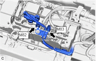
- Disconnect the M82 and M83 No. 2 floor wire connectors.
HINT:
Make sure that no foreign matter has entered or contaminated the No. 2 floor wire.
- Using a megohmmeter set to 500 V, measure the resistance according to the value(s) in the table below.NOTE:
Be sure to set the megohmmeter to 500 V when performing this test. Using a setting higher than 500 V can result in damage to the component being inspected.
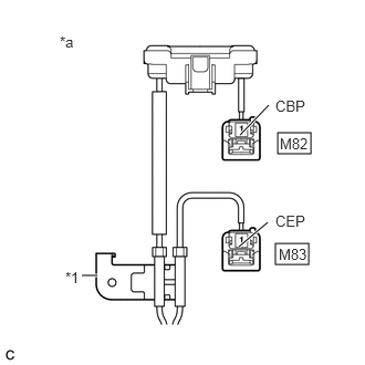
Standard Resistance
Tester Connection Condition Specified Condition M82-1 (CBP) - Body ground and shield ground Ignition switch off 10 MΩ or higher M83-1 (CEP) - Body ground and shield ground Ignition switch off 10 MΩ or higher HINT:
Visually inspect the No. 2 floor wire for damage. If there is any damage, then this is the likely cause of low insulation resistance.
*1 Shield Ground *a No. 2 Floor Wire
(HV Battery Junction Block Assembly Side)Result
Proceed to OK NG
Result:
NG
See step 34
Result:
OK
See step 33
- Check that the service plug grip is not installed.
- REPLACE HV BATTERY JUNCTION BLOCK ASSEMBLY
Refer to REMOVAL [12/2019 - 10/2022] , or refer to REMOVAL [10/2022 - 11/2023]
Result
Proceed to NEXT Result:
NEXT
PERFORM CONFIRMATION AFTER REPLACING PARTS
Refer to CONFIRMATION DRIVING PATTERN
- CHECK NO. 2 FLOOR WIRE WARNING:
Be sure to wear insulated gloves.
- Check that the service plug grip is not installed.NOTE:
After removing the service plug grip, do not turn the ignition switch to ON (READY), unless instructed by the repair information because this may cause a malfunction.
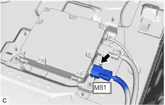
- Disconnect the M81 No. 2 floor wire connector from the voltage inverter assembly.
HINT:
Make sure that no foreign matter has entered or contaminated the No. 2 floor wire.
- Using a megohmmeter set to 500 V, measure the resistance according to the value(s) in the table below.NOTE:
Be sure to set the megohmmeter to 500 V when performing this test. Using a setting higher than 500 V can result in damage to the component being inspected.
Standard Resistance
Tester Connection Condition Specified Condition M82-1 (CBP) - Body ground and shield ground Ignition switch off 10 MΩ or higher M83-1 (CEP) - Body ground and shield ground Ignition switch off 10 MΩ or higher HINT:
Visually inspect the No. 2 floor wire for damage. If there is any damage, then this is the likely cause of low insulation resistance.
*1 Shield Ground *a No. 2 Floor Wire
(HV Battery Junction Block Assembly Side)Result
Proceed to OK NG
Result:
NG
See step 36
Result:
OK
See step 35
- Check that the service plug grip is not installed.
- REPLACE VOLTAGE INVERTER ASSEMBLY
Refer to REMOVAL [12/2019 - 10/2022] , or refer to REMOVAL [10/2022 - 11/2023]
Result
Proceed to NEXT Result:
NEXT
PERFORM CONFIRMATION AFTER REPLACING PARTS
Refer to CONFIRMATION DRIVING PATTERN
- REPLACE NO. 2 FLOOR WIRE
Result
Proceed to NEXT Result:
NEXT
PERFORM CONFIRMATION AFTER REPLACING PARTS
Refer to CONFIRMATION DRIVING PATTERN
- REPLACE FLOOR UNDER WIRE
Refer to REMOVAL [12/2019 - 10/2022] , or refer to REMOVAL [10/2022 - 11/2023]
Result
Proceed to NEXT Result:
NEXT
PERFORM CONFIRMATION AFTER REPLACING PARTS
Refer to CONFIRMATION DRIVING PATTERN
- CHECK INVERTER WITH CONVERTER ASSEMBLY WARNING:
Be sure to wear insulated gloves.
- Check that the service plug grip is not installed.NOTE:
After removing the service plug grip, do not turn the ignition switch to ON (READY), unless instructed by the repair information because this may cause a malfunction.
- Disconnect the HV floor under wire (rear traction motor cable) from the inverter with converter assembly.
HINT:
Make sure that no foreign matter, coolant or water enters the inverter with converter assembly.
- Using a megohmmeter set to 500 V, measure the resistance according to the value(s) in the table below.NOTE:
Be sure to set the megohmmeter to 500 V when performing this test. Using a setting higher than 500 V can result in damage to the component being inspected.
Standard Resistance
Tester Connection Condition Specified Condition High voltage terminal - Body ground Ignition switch off 1 MΩ or higher HINT:
Perform this inspection with the HV floor under wire (rear traction motor cable) disconnected from the inverter with converter assembly.
*a High Voltage Terminal Result
Proceed to OK NG
Result:
NG
See step 42
Result:
OK
See step 39
- Check that the service plug grip is not installed.
- CHECK FLOOR UNDER WIRE (REAR TRACTION MOTOR CABLE) WARNING:
Be sure to wear insulated gloves.
- Check that the service plug grip is not installed.NOTE:
After removing the service plug grip, do not turn the ignition switch to ON (READY), unless instructed by the repair information because this may cause a malfunction.
- Remove the HV floor under wire (rear traction motor cable) from the rear traction motor with transaxle assembly.
Refer to REMOVAL [12/2019 - 10/2022] , or refer to REMOVAL [10/2022 - 11/2023]
- Using a megohmmeter set to 500 V, measure the resistance according to the value(s) in the table below.NOTE:
Be sure to set the megohmmeter to 500 V when performing this test. Using a setting higher than 500 V can result in damage to the component being inspected.
Standard Resistance
Tester Connection Condition Specified Condition k4-2 (R-U) - Shield ground Ignition switch off 100 MΩ or higher k4-1 (R-V) - Shield ground Ignition switch off 100 MΩ or higher k4-3 (R-W) - Shield ground Ignition switch off 100 MΩ or higher *1 Shield Ground *a HV Floor Under Wire (Rear Traction Motor Cable)
(Inverter with Converter Assembly Side)Result
Proceed to OK NG
Result:
NG
See step 44
Result:
OK
See step 40
- Check that the service plug grip is not installed.
- CHECK REAR TRACTION MOTOR CABLE WARNING:
Be sure to wear insulated gloves.
- Check that the service plug grip is not installed.NOTE:
After removing the service plug grip, do not turn the ignition switch to ON (READY), unless instructed by the repair information because this may cause a malfunction.
- Remove the rear traction motor cable from the rear traction motor with transaxle assembly.
Refer to REMOVAL [12/2019 - 10/2022] , or refer to REMOVAL [10/2022 - 11/2023]
- Using a megohmmeter set to 500 V, measure the resistance according to the value(s) in the table below.NOTE:
Be sure to set the megohmmeter to 500 V when performing this test. Using a setting higher than 500 V can result in damage to the component being inspected.
Standard Resistance
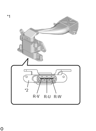
Tester Connection Condition Specified Condition R-W - Shield ground Ignition switch off 100 MΩ or higher R-V - Shield ground Ignition switch off 100 MΩ or higher R-U - Shield ground Ignition switch off 100 MΩ or higher *1 Rear Traction Motor Cable *2 Shield Ground - Install the rear traction motor cable.
Result
Proceed to OK NG
Result:
NG
See step 43
Result:
OK
See step 41
- Check that the service plug grip is not installed.
- REPLACE REAR TRACTION MOTOR WITH TRANSAXLE ASSEMBLY
Refer to REMOVAL [12/2019 - 10/2022] , or refer to REMOVAL [10/2022 - 11/2023]
Result
Proceed to NEXT Result:
NEXT
PERFORM CONFIRMATION AFTER REPLACING PARTS
Refer to CONFIRMATION DRIVING PATTERN
- REPLACE INVERTER WITH CONVERTER ASSEMBLY
Refer to REMOVAL [12/2019 - 10/2022] , or refer to REMOVAL [10/2022 - 11/2023]
Result
Proceed to NEXT Result:
NEXT
PERFORM CONFIRMATION AFTER REPLACING PARTS
Refer to CONFIRMATION DRIVING PATTERN
- REPLACE REAR TRACTION MOTOR CABLE
Refer to REMOVAL [12/2019 - 10/2022] , or refer to REMOVAL [10/2022 - 11/2023]
Result
Proceed to NEXT Result:
NEXT
PERFORM CONFIRMATION AFTER REPLACING PARTS
Refer to CONFIRMATION DRIVING PATTERN
- REPLACE FLOOR UNDER WIRE
Refer to REMOVAL [12/2019 - 10/2022] , or refer to REMOVAL [10/2022 - 11/2023]
Result
Proceed to NEXT Result:
NEXT
PERFORM CONFIRMATION AFTER REPLACING PARTS
Refer to CONFIRMATION DRIVING PATTERN