DTC P0705-62: Transmission Range Sensor "A" Circuit (PRNDL Input) Signal Compare Failure [12/2019 - 11/2023]: Procedure
- READ VALUE USING GTS (SHIFT POSITION SENSOR)
- While slowly moving the shift lever from P to S, then back to P, read the Data List (Shift Position Sensor) displayed on the GTS.
Powertrain > Hybrid Control > Data List
Tester Display Shift Position Sensor (PNB) Shift Position Sensor (PR) Shift Position Sensor (DB1) Shift Position Sensor (DB2) Shift Position Sensor (N) Shift Position Sensor (R) Shift Position Sensor (P) HINT:
Be sure to move the shift lever slowly.
Standard
Data List Shift Position P R N D or S Shift Position Sensor (P) ON OFF OFF OFF Shift Position Sensor (R) OFF ON OFF OFF Shift Position Sensor (PR) ON ON OFF OFF Shift Position Sensor (N) OFF OFF ON OFF Shift Position Sensor (DB1) OFF OFF OFF ON Shift Position Sensor (DB2) OFF OFF OFF ON Shift Position Sensor (PNB) ON OFF ON OFF - Check for DTCs.
Powertrain > Hybrid Control > Trouble Codes
OK
DTC P0705-62 is not output.
- Turn the ignition switch off.
Result
Proceed to OK NG
Result:
NG
See step 3
Result:
OK
See step 2
- While slowly moving the shift lever from P to S, then back to P, read the Data List (Shift Position Sensor) displayed on the GTS.
- CHECK FOR INTERMITTENT PROBLEMS
Refer to CHECK FOR INTERMITTENT PROBLEMS [12/2019 - 11/2023]
Result
Proceed to OK NG Result:
OK
REPLACE HYBRID VEHICLE CONTROL ECU. Refer to REMOVAL [12/2019 - 10/2022] , or refer to REMOVAL [10/2022 - 11/2023]
Result:
NG
REPAIR OR REPLACE MALFUNCTIONING PARTS, COMPONENT AND AREA
- INSPECT SHIFT LEVER POSITION SENSOR
- Turn the ignition switch to ON.
- Measure the voltage according to the value(s) in the table below.
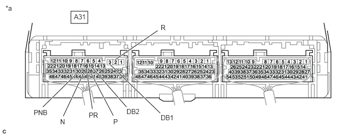
*a Component with harness connected
(Hybrid Vehicle Control ECU)- - Standard Voltage
Tester Connection Condition Specified Condition A31-28 (P) - Body ground Ignition switch ON
Shift lever in P6.0 to 14 V Ignition switch ON
Shift lever in any position except P0 to 1.5 V A31-2 (R) - Body ground Ignition switch ON
Shift lever in R6.0 to 14 V Ignition switch ON
Shift lever in any position except R0 to 1.5 V A31-29 (N) - Body ground Ignition switch ON
Shift lever in N6.0 to 14 V Ignition switch ON
Shift lever in any position except N0 to 1.5 V A31-3 (DB1) - Body ground Ignition switch ON
Shift lever in D or S6.0 to 14 V Ignition switch ON
Shift lever in any position except D or S0 to 1.5 V A31-15 (DB2) - Body ground Ignition switch ON
Shift lever in D or S6.0 to 14 V Ignition switch ON
Shift lever in any position except D or S0 to 1.5 V A31-16 (PR) - Body ground Ignition switch ON
Shift lever in P or R6.0 to 14 V Ignition switch ON
Shift lever in any position except P or R0 to 1.5 V A31-30 (PNB) - Body ground Ignition switch ON
Shift lever in P or N6.0 to 14 V Ignition switch ON
Shift lever in any position except P or N0 to 1.5 V - Turn the ignition switch off.
Result
Proceed to OK NG
Result:
OK
REPLACE HYBRID VEHICLE CONTROL ECU. Refer to REMOVAL [12/2019 - 10/2022] , or refer to REMOVAL [10/2022 - 11/2023]
Result:
NG
See step 4
- CHECK HARNESS AND CONNECTOR (POWER SOURCE CIRCUIT)
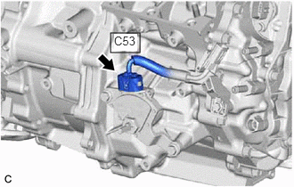
- Disconnect the C53 shift lever position sensor connector.
- Turn the ignition switch to ON.
- Measure the voltage according to the value(s) in the table below.
Standard Voltage
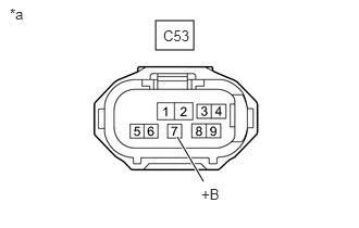
Tester Connection Condition Specified Condition C53-7 (+B) - Body ground Ignition switch ON 6.0 to 14 V *a Front view of wire harness connector
(to Shift Lever Position Sensor)NOTE:Turning the ignition switch to ON with the shift lever position sensor connector disconnected causes other DTCs to be stored. Clear the DTCs after performing this inspection.
- Turn the ignition switch off.
- Reconnect the C53 shift lever position sensor connector.
Result
Proceed to OK NG
Result:
NG
See step 6
Result:
OK
See step 5
- Disconnect the C53 shift lever position sensor connector.
- INSPECT SHIFT LEVER POSITION SENSOR
Refer to INSPECTION [12/2019 - ]
Result
Proceed to OK NG Result:
OK
REPAIR OR REPLACE HARNESS OR CONNECTOR
Result:
NG
REPLACE SHIFT LEVER POSITION SENSOR. Refer to REMOVAL [12/2019 - ]
- CHECK HARNESS AND CONNECTOR (SHIFT LEVER POSITION SENSOR - HYBRID VEHICLE CONTROL ECU)
- Disconnect the C53 shift lever position sensor connector.
- Disconnect the A31 hybrid vehicle control ECU connector.
- Measure the resistance according to the value(s) in the table below.
Standard Resistance
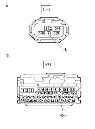
Tester Connection Condition Specified Condition C53-7 (+B) - A31-18 (PSFT) Ignition switch off Below 1 Ω C53-7 (+B) or A31-18 (PSFT) - Body ground and other terminals Ignition switch off 10 kΩ or higher *a Front view of wire harness connector
(to Shift Lever Position Sensor)*b Front view of wire harness connector
(to Hybrid Vehicle Control ECU) - Reconnect the A31 hybrid vehicle control ECU connector.
- Reconnect the C53 shift lever position sensor connector.
Result
Proceed to OK NG
Result:
OK
REPLACE HYBRID VEHICLE CONTROL ECU. Refer to REMOVAL [12/2019 - 10/2022] , or refer to REMOVAL [10/2022 - 11/2023]
Result:
NG
REPAIR OR REPLACE HARNESS OR CONNECTOR