DTC P0A30-11: Drive Motor "B" Temperature Sensor Circuit Short to Ground; DTC P0A30-15: Drive Motor "B" Temperature Sensor Circuit Short to Battery or Open [12/2019 - 11/2023]: Procedure
- CHECK CONNECTOR CONNECTION CONDITION (HYBRID VEHICLE CONTROL ECU CONNECTOR)
See step 1
Result
Result Proceed to OK A NG (The connector is not connected securely.) B NG (The terminals are not making secure contact or are deformed, or water or foreign matter exists in the connector.) C Result:
B
CONNECT SECURELY
Result:
C
REPAIR OR REPLACE HARNESS OR CONNECTOR
Result:
A
See step 2
- CHECK CONNECTOR CONNECTION CONDITION (NO. 2 FLOOR WIRE CONNECTOR)
- Check the connection condition of the No. 2 floor wire connector and the contact pressure of each terminal. Check the terminal for deformation, and check the connector for water ingress and foreign matter.
Refer to ELECTRONIC CIRCUIT INSPECTION PROCEDURE [12/2019 - ]
OK
- The connector is connected securely.
- The terminals are not deformed and are connected securely.
- No water or foreign matter in the connectors.
Result
Result Proceed to OK A NG (The connector is not connected securely.) B NG (The terminals are not making secure contact or are deformed, or water or foreign matter exists in the connector.) C
Result:
B
CONNECT SECURELY
Result:
C
REPAIR OR REPLACE HARNESS OR CONNECTOR
Result:
A
See step 3
- Check the connection condition of the No. 2 floor wire connector and the contact pressure of each terminal. Check the terminal for deformation, and check the connector for water ingress and foreign matter.
- CHECK CONNECTOR CONNECTION CONDITION (FRAME WIRE CONNECTOR)
- Check the connection condition of the frame wire connector and the contact pressure of each terminal. Check the terminals for deformation, and check the connector for water ingress and foreign matter.
Refer to ELECTRONIC CIRCUIT INSPECTION PROCEDURE [12/2019 - ]
OK
- The connector is connected securely.
- The terminals are not deformed and are connected securely.
- No water or foreign matter in the connector.
Result
Result Proceed to OK A NG (The connector is not connected securely.) B NG (The terminals are not making secure contact or are deformed, or water or foreign matter exists in the connector.) C
Result:
B
CONNECT SECURELY
Result:
C
REPAIR OR REPLACE HARNESS OR CONNECTOR
Result:
A
See step 4
- Check the connection condition of the frame wire connector and the contact pressure of each terminal. Check the terminals for deformation, and check the connector for water ingress and foreign matter.
- READ VALUE USING GTS (REAR MOTOR TEMPERATURE)
- Read the Data List.
Powertrain > Hybrid Control > Data List
Tester Display Rear Motor Temperature Result
Result Proceed to -40°C (-40°F) A 215°C (419°F) B Same as actual temperature C - Turn the ignition switch off.
Result:
B
See step 9
Result:
C
REPAIR OR REPLACE HARNESS OR CONNECTOR
Result:
A
See step 5
- Read the Data List.
- READ VALUE USING GTS (CHECK WIRE HARNESS OPEN CIRCUIT)
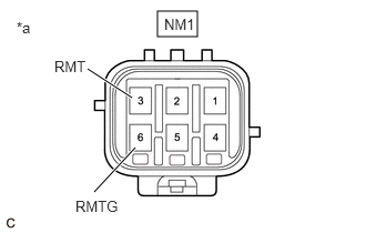
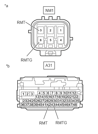
- Disconnect the NM1 frame wire connector.
- Connect terminals 6 (RMTG) and 3 (RMT) of the NM1 frame wire connector (hybrid vehicle control ECU side).
*a Front view of frame wire connector
(Hybrid Vehicle Control ECU Side) - Read the Data List.
Powertrain > Hybrid Control > Data List
Tester Display Rear Motor Temperature OK
Tester Display Condition Specified Condition Rear Motor Temperature Terminals NM1-6 (RMTG) and NM1-3 (RMT) connected
Ignition switch ON215°C (419°F) - Turn the ignition switch off.
- Reconnect the NM1 frame wire connector.
Result
Proceed to OK NG
Result:
NG
See step 8
Result:
OK
See step 6
- CHECK CONNECTOR CONNECTION CONDITION (REAR MOTOR TEMPERATURE SENSOR CONNECTOR)
- Remove the rear suspension member sub-assembly.
Refer to REMOVAL [12/2019 - 10/2022] , or refer to REMOVAL [10/2022 - 11/2023]
- Check the connection condition of the rear motor temperature sensor connector and the contact pressure of each terminal. Check the terminals for deformation, and check the connector for water ingress and foreign matter.
Refer to ELECTRONIC CIRCUIT INSPECTION PROCEDURE [12/2019 - ]
OK
- The connector is connected securely.
- The terminals are not deformed and are connected securely.
- No water or foreign matter in the connector.
Result
Result Proceed to OK A NG (The connector is not connected securely.) B NG (The terminals are not making secure contact or are deformed, or water or foreign matter exists in the connector.) C - Reinstall the rear suspension member sub-assembly.
Result:
B
CONNECT SECURELY
Result:
C
REPAIR OR REPLACE HARNESS OR CONNECTOR
Result:
A
See step 7
- Remove the rear suspension member sub-assembly.
- INSPECT REAR TRACTION MOTOR WITH TRANSAXLE ASSEMBLY (REAR MOTOR TEMPERATURE SENSOR)
- Remove the rear suspension member sub-assembly.
Refer to REMOVAL [12/2019 - 10/2022] , or refer to REMOVAL [10/2022 - 11/2023]
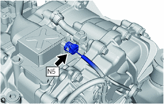
- Disconnect the N5 rear motor temperature sensor connector.
- Measure the resistance according to the value(s) in the table below.
Standard Resistance
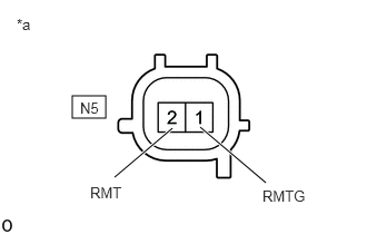
Tester Connection Condition Specified Condition N5-1 (RMTG) - N5-2 (RMT) Ignition switch off 0.4 to 2100 kΩ - Reconnect the N5 rear motor temperature sensor connector.
*a Component without harness connected
(Rear Motor Temperature Sensor (Rear Traction Motor with Transaxle Assembly)) - Reinstall the rear suspension member sub-assembly.
Result
Proceed to OK NG
Result:
OK
REPAIR OR REPLACE HARNESS OR CONNECTOR (REAR MOTOR TEMPERATURE SENSOR - NO. 2 FLOOR WIRE)
Result:
NG
REPLACE REAR TRACTION MOTOR WITH TRANSAXLE ASSEMBLY. Refer to REMOVAL [12/2019 - 10/2022] , or refer to REMOVAL [10/2022 - 11/2023]
- Remove the rear suspension member sub-assembly.
- CHECK HYBRID VEHICLE CONTROL ECU
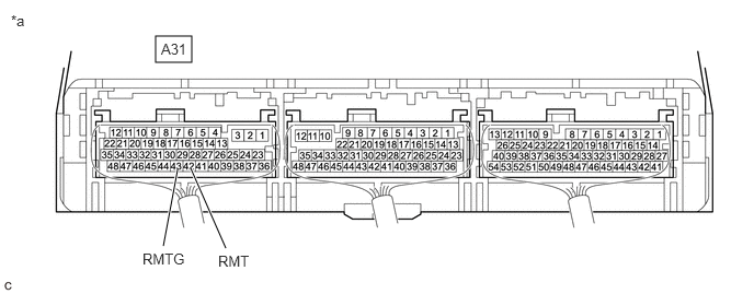
- Connect terminals 42 (RMT) and 43 (RMTG) of the A31 hybrid vehicle control ECU connector.
*a Component with harness connected
(Hybrid Vehicle Control ECU)- - - Read the Data List.
Powertrain > Hybrid Control > Data List
Tester Display Rear Motor Temperature OK
Tester Display Condition Specified Condition Rear Motor Temperature Terminals A31-42 (RMT) and A31-43 (RMTG) connected
Ignition switch ON215°C (419°F) - Turn the ignition switch off.
Result
Proceed to OK NG
Result:
OK
REPAIR OR REPLACE HARNESS OR CONNECTOR (FRAME WIRE - HYBRID VEHICLE CONTROL ECU)
Result:
NG
REPLACE HYBRID VEHICLE CONTROL ECU. Refer to REMOVAL [12/2019 - 10/2022] , or refer to REMOVAL [10/2022 - 11/2023]
- Connect terminals 42 (RMT) and 43 (RMTG) of the A31 hybrid vehicle control ECU connector.
- READ VALUE USING GTS (CHECK WIRE HARNESS SHORT CIRCUIT)
- Disconnect the NM1 frame wire connector.
- Read the Data List.
Powertrain > Hybrid Control > Data List
Tester Display Rear Motor Temperature OK
Tester Display Switch Condition Specified Condition Rear Motor Temperature Ignition switch ON -40°C - Turn the ignition switch off.
- Reconnect the NM1 frame wire connector.
Result
Proceed to OK NG
Result:
NG
See step 12
Result:
OK
See step 10
- CHECK CONNECTOR CONNECTION CONDITION (REAR MOTOR TEMPERATURE SENSOR CONNECTOR)
- Remove the rear suspension member sub-assembly.
Refer to REMOVAL [12/2019 - 10/2022] , or refer to REMOVAL [10/2022 - 11/2023]
- Check the connection condition of the rear motor temperature sensor connector and the contact pressure of each terminal. Check the terminals for deformation, and check the connector for water ingress and foreign matter.
Refer to ELECTRONIC CIRCUIT INSPECTION PROCEDURE [12/2019 - ]
OK
- The connector is connected securely.
- The terminals are not deformed and are connected securely.
- No water or foreign matter in the connector.
Result
Result Proceed to OK A NG (The connector is not connected securely.) B NG (The terminals are not making secure contact or are deformed, or water or foreign matter exists in the connector.) C - Reinstall the rear suspension member sub-assembly.
Result:
B
CONNECT SECURELY
Result:
C
REPAIR OR REPLACE HARNESS OR CONNECTOR
Result:
A
See step 11
- Remove the rear suspension member sub-assembly.
- INSPECT REAR TRACTION MOTOR WITH TRANSAXLE ASSEMBLY (REAR MOTOR TEMPERATURE SENSOR)
- Remove the rear suspension member sub-assembly.
Refer to REMOVAL [12/2019 - 10/2022] , or refer to REMOVAL [10/2022 - 11/2023]
- Disconnect the N5 rear motor temperature sensor connector.
- Measure the resistance according to the value(s) in the table below.
Standard Resistance
Tester Connection Condition Specified Condition N5-1 (RMTG) - N5-2 (RMT) Ignition switch off 0.4 to 2100 kΩ - Reconnect the N5 rear motor temperature sensor connector.
*a Component without harness connected
(Rear Motor Temperature Sensor (Rear Traction Motor with Transaxle Assembly)) - Reinstall the rear suspension member sub-assembly.
Result
Proceed to OK NG
Result:
OK
REPAIR OR REPLACE HARNESS OR CONNECTOR (REAR MOTOR TEMPERATURE SENSOR - FRAME WIRE)
Result:
NG
REPLACE REAR TRACTION MOTOR WITH TRANSAXLE ASSEMBLY. Refer to REMOVAL [12/2019 - 10/2022] , or refer to REMOVAL [10/2022 - 11/2023]
- Remove the rear suspension member sub-assembly.
- CHECK HARNESS AND CONNECTOR (FRAME WIRE - HYBRID VEHICLE CONTROL ECU)
- Disconnect the NM1 frame wire connector.
- Disconnect the A31 hybrid vehicle control ECU connector.
- Measure the resistance according to the value(s) in the table below.
*a Front view of frame wire connector
(Hybrid Vehicle Control ECU Side)*b Front view of wire harness connector
(to Hybrid Vehicle Control ECU)Standard Resistance (Check for Open)
Tester Connection Condition Specified Condition NM1-6 (RMTG) - A31-43 (RMTG) Ignition switch off Below 1 Ω NM1-3 (RMT) - A31-42 (RMT) Ignition switch off Below 1 Ω Standard Resistance (Check for Short)
Tester Connection Condition Specified Condition NM1-6 (RMTG) or A31-43 (RMTG) - Body ground and other terminals Ignition switch off 10 kΩ or higher NM1-3 (RMT) or A31-42 (RMT) - Body ground and other terminals Ignition switch off 10 kΩ or higher - Reconnect the A31 hybrid vehicle control ECU connector.
- Reconnect the NM1 frame wire connector.
Result
Proceed to OK NG
Result:
OK
REPLACE HYBRID VEHICLE CONTROL ECU. Refer to REMOVAL [12/2019 - 10/2022] , or refer to REMOVAL [10/2022 - 11/2023]
Result:
NG
REPAIR OR REPLACE HARNESS OR CONNECTOR