DTC P0A30-2A: Drive Motor "B" Temperature Sensor Signal Stuck In Range [12/2019 - 11/2023]: Procedure
- CHECK DTC OUTPUT (HYBRID CONTROL)
- Check for DTCs.
Powertrain > Hybrid Control > Trouble Codes
Result
Result Proceed to No DTCs are output, or DTCs except the ones in the table below are also output. A Any of the following DTCs are also output. B Relevant DTC P0A30-11 Drive Motor "B" Temperature Sensor Circuit Short to Ground P0A30-15 Drive Motor "B" Temperature Sensor Circuit Short to Battery or Open - Turn the ignition switch off.
Result:
B
GO TO DTC CHART (HYBRID CONTROL SYSTEM). Refer to DIAGNOSTIC TROUBLE CODE CHART [12/2019 - 09/2020] , or refer to DIAGNOSTIC TROUBLE CODE CHART [09/2020 - 10/2021] , or refer to DIAGNOSTIC TROUBLE CODE CHART [10/2021 - 11/2023]
Result:
A
See step 2
- Check for DTCs.
- CHECK CONNECTOR CONNECTION CONDITION (HYBRID VEHICLE CONTROL ECU CONNECTOR)
See step 1
Result
Result Proceed to OK A NG (The connector is not connected securely.) B NG (The terminals are not making secure contact or are deformed, or water or foreign matter exists in the connector.) C Result:
B
CONNECT SECURELY
Result:
C
REPAIR OR REPLACE HARNESS OR CONNECTOR
Result:
A
See step 3
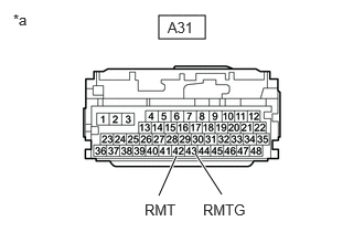
- CHECK HARNESS AND CONNECTOR (REAR MOTOR TEMPERATURE SENSOR - HYBRID VEHICLE CONTROL ECU)
- Disconnect the A31 hybrid vehicle control ECU connector.
- Measure the resistance according to the value(s) in the table below.
*a Front view of wire harness connector
(to Hybrid Vehicle Control ECU)Standard Resistance
Tester Connection Condition Specified Condition A31-42 (RMT) - A31-43 (RMTG) Ignition switch off 0.4 to 2100 kΩ - Reconnect the A31 hybrid vehicle control ECU connector.
Result
Proceed to OK NG
Result:
NG
See step 10
Result:
OK
See step 4
- CHECK CONNECTOR CONNECTION CONDITION (NO. 2 FLOOR WIRE CONNECTOR)
See step 2
Result
Result Proceed to OK A NG (The connector is not connected securely.) B NG (The terminals are not making secure contact or are deformed, or water or foreign matter exists in the connector.) C Result:
B
CONNECT SECURELY
Result:
C
REPAIR OR REPLACE HARNESS OR CONNECTOR
Result:
A
See step 5
- CHECK HARNESS AND CONNECTOR (HYBRID VEHICLE CONTROL ECU - NO. 2 FLOOR WIRE)
- Disconnect the AM9 No. 2 floor wire connector.
- Disconnect the A31 hybrid vehicle control ECU connector.
- Measure the resistance according to the value(s) in the table below.
HINT:
When performing the measurement, lightly jiggle the wire harness up and down and left and right and confirm that the resistance does not fluctuate.
Standard Resistance (Check for Open)
Tester Connection Condition Specified Condition AM9-10 (RMT) - A31-42 (RMT) Ignition switch off Below 1 Ω AM9-11 (RMTG) - A31-43 (RMTG) Ignition switch off Below 1 Ω Standard Resistance (Check for Short)
Tester Connection Condition Specified Condition AM9-10 (RMT) or A31-42 (RMT) - Body ground and other terminals Ignition switch off 10 kΩ or higher AM9-11 (RMTG) or A31-43 (RMTG) - Body ground and other terminals Ignition switch off 10 kΩ or higher - Reconnect the A31 hybrid vehicle control ECU connector.
- Reconnect the AM9 No. 2 floor wire connector.
Result
Proceed to OK NG
Result:
NG
REPAIR OR REPLACE HARNESS OR CONNECTOR
Result:
OK
See step 6
- CHECK CONNECTOR CONNECTION CONDITION (FRAME WIRE CONNECTOR)
See step 3
Result
Result Proceed to OK A NG (The connector is not connected securely.) B NG (The terminals are not making secure contact or are deformed, or water or foreign matter exists in the connector.) C Result:
B
CONNECT SECURELY
Result:
C
REPAIR OR REPLACE HARNESS OR CONNECTOR
Result:
A
See step 7
- CHECK HARNESS AND CONNECTOR (FRAME WIRE - NO. 2 FLOOR WIRE)
- Disconnect the NM1 frame wire connector.
- Disconnect the AM9 No. 2 floor wire connector.
- Measure the resistance according to the value(s) in the table below.
HINT:
When performing the measurement, lightly jiggle the wire harness up and down and left and right and confirm that the resistance does not fluctuate.
Standard Resistance (Check for Open)
Tester Connection Condition Specified Condition NM1-3 (RMT) - AM9-10 (RMT) Ignition switch off Below 1 Ω NM1-6 (RMTG) - AM9-11 (RMTG) Ignition switch off Below 1 Ω Standard Resistance (Check for Short)
Tester Connection Condition Specified Condition NM1-3 (RMT) or AM9-10 (RMT) - Body ground and other terminals Ignition switch off 10 kΩ or higher NM1-6 (RMTG) or AM9-11 (RMTG) - Body ground and other terminals Ignition switch off 10 kΩ or higher - Reconnect the NM1 frame wire connector.
- Reconnect the AM9 No. 2 floor wire connector.
Result
Proceed to OK NG
Result:
NG
REPAIR OR REPLACE HARNESS OR CONNECTOR
Result:
OK
See step 8
- CHECK CONNECTOR CONNECTION CONDITION (REAR MOTOR TEMPERATURE SENSOR CONNECTOR)
See step 6
Result
Result Proceed to OK A NG (The connector is not connected securely.) B NG (The terminals are not making secure contact or are deformed, or water or foreign matter exists in the connector.) C Result:
B
CONNECT SECURELY
Result:
C
REPAIR OR REPLACE HARNESS OR CONNECTOR
Result:
A
See step 9
- CHECK HARNESS AND CONNECTOR (REAR MOTOR TEMPERATURE SENSOR - FRAME WIFE)
- Disconnect the NM1 frame wire connector.
- Remove the rear suspension member sub-assembly.
Refer to REMOVAL [12/2019 - 10/2022] , or refer to REMOVAL [10/2022 - 11/2023]
- Disconnect the N5 rear motor temperature sensor connector.
- Measure the resistance according to the value(s) in the table below.
Standard Resistance (Check for Open)
Tester Connection Condition Specified Condition N5-2 (RMT) - NM1-3 (RMT) Ignition switch off Below 1 Ω N5-1 (RMTG) - NM1-6 (RMTG) Ignition switch off Below 1 Ω Standard Resistance (Check for Short)
Tester Connection Condition Specified Condition N5-2 (RMT) or NM1-3 (RMT) - Body ground and other terminals Ignition switch off 10 kΩ or higher N5-1 (RMTG) or NM1-6 (RMTG) - Body ground and other terminals Ignition switch off 10 kΩ or higher - Reconnect the N5 rear motor temperature sensor connector.
- Reinstall the rear suspension member sub-assembly.
- Reconnect the NM1 frame wire connector.
Result
Proceed to OK NG
Result:
OK
REPLACE REAR TRACTION MOTOR WITH TRANSAXLE ASSEMBLY. Refer to REMOVAL [12/2019 - 10/2022] , or refer to REMOVAL [10/2022 - 11/2023]
Result:
NG
REPAIR OR REPLACE HARNESS OR CONNECTOR
- INSPECT REAR TRACTION MOTOR WITH TRANSAXLE ASSEMBLY (REAR MOTOR TEMPERATURE SENSOR)
- Disconnect the AM9 No. 2 floor wire connector.
- Measure the resistance according to the value(s) in the table below.
Standard Resistance
Tester Connection Condition Specified Condition AM9-10 (RMT) - AM9-11 (RMTG) Ignition switch off 0.4 to 2100 kΩ - Reconnect the AM9 No. 2 floor wire connector.
Result
Proceed to OK NG
Result:
OK
REPAIR OR REPLACE HARNESS OR CONNECTOR (NO. 2 FLOOR WIRE - HYBRID VEHICLE CONTROL ECU)
Result:
NG
See step 11
- INSPECT REAR TRACTION MOTOR WITH TRANSAXLE ASSEMBLY (REAR MOTOR TEMPERATURE SENSOR)
- Disconnect the NM1 frame wire connector.
- Measure the resistance according to the value(s) in the table below.
Standard Resistance
Tester Connection Condition Specified Condition NM1-3 (RMT) - NM1-6 (RMTG) Ignition switch off 0.4 to 2100 kΩ - Reconnect the NM1 frame wire connector.
Result
Proceed to OK NG
Result:
OK
REPAIR OR REPLACE HARNESS OR CONNECTOR (FRAME WIRE - NO. 2 FLOOR WIRE)
Result:
NG
See step 12
- INSPECT REAR TRACTION MOTOR WITH TRANSAXLE ASSEMBLY (REAR MOTOR TEMPERATURE SENSOR)
See step 11
Result
Proceed to OK NG Result:
OK
REPAIR OR REPLACE HARNESS OR CONNECTOR (REAR MOTOR TEMPERATURE SENSOR - FRAME WIRE)
Result:
NG
REPLACE REAR TRACTION MOTOR WITH TRANSAXLE ASSEMBLY. Refer to REMOVAL [12/2019 - 10/2022] , or refer to REMOVAL [10/2022 - 11/2023]