DTC B242E: Open in IG Circuit [12/2019 - 11/2023]: Procedure
- CLEAR DTC
- Clear the DTCs.
Body Electrical > AFS > Clear DTCs
Body Electrical > AFS (Sub) > Clear DTCs
Result
Proceed to NEXT
Result:
NEXT
See step 2
- Clear the DTCs.
- CHECK FOR DTC
- Turn the ignition switch to ON.
- Wait 10 seconds or more.
- Check for DTCs.
Body Electrical > AFS > Trouble Codes
Body Electrical > AFS (Sub) > Trouble Codes
OK
DTC B242E is not output.
Result
Result Proceed to OK A NG (DTC output from headlight ECU sub-assembly LH) B NG (DTC output from headlight ECU sub-assembly RH) C
Result:
A
USE SIMULATION METHOD TO CHECK. Refer to HOW TO PROCEED WITH TROUBLESHOOTING [12/2019 - ]
Result:
C
See step 5
Result:
B
See step 3
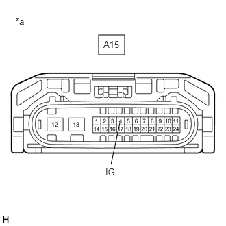
- INSPECT HEADLIGHT ECU SUB-ASSEMBLY LH (IG TERMINAL VOLTAGE)
*a Front view of wire harness connector
(to Headlight ECU Sub-assembly LH)- Disconnect the A15 headlight ECU sub-assembly LH connector.
- Measure the voltage according to the value(s) in the table below.
Standard Voltage
Tester Connection Condition Specified Condition A15-4 (IG) - Body ground Ignition switch ON 11 to 14 V Result
Proceed to OK NG
Result:
NG
REPAIR OR REPLACE HARNESS OR CONNECTOR
Result:
OK
See step 4
- CHECK HARNESS AND CONNECTOR (HEADLIGHT ECU SUB-ASSEMBLY LH - BODY GROUND)
- Measure the resistance according to the value(s) in the table below.
Standard Resistance
Tester Connection Condition Specified Condition A15-12 (GND) - Body ground Always Below 1 Ω Result
Proceed to OK NG
Result:
OK
REPLACE HEADLIGHT ECU SUB-ASSEMBLY LH. Refer to REMOVAL [12/2019 - 11/2023]
Result:
NG
REPAIR OR REPLACE HARNESS OR CONNECTOR
- Measure the resistance according to the value(s) in the table below.
- INSPECT HEADLIGHT ECU SUB-ASSEMBLY RH (IG TERMINAL VOLTAGE)
*a Front view of wire harness connector
(to Headlight ECU Sub-assembly RH)- Disconnect the A16 headlight ECU sub-assembly RH connector.
- Measure the voltage according to the value(s) in the table below.
Standard Voltage
Tester Connection Condition Specified Condition A16-4 (IG) - Body ground Ignition switch ON 11 to 14 V Result
Proceed to OK NG
Result:
NG
REPAIR OR REPLACE HARNESS OR CONNECTOR
Result:
OK
See step 6
- CHECK HARNESS AND CONNECTOR (HEADLIGHT ECU SUB-ASSEMBLY RH - BODY GROUND)
- Measure the resistance according to the value(s) in the table below.
Standard Resistance
Tester Connection Condition Specified Condition A16-12 (GND) - Body ground Always Below 1 Ω Result
Proceed to OK NG
Result:
OK
REPLACE HEADLIGHT ECU SUB-ASSEMBLY RH. Refer to REMOVAL [12/2019 - 11/2023]
Result:
NG
REPAIR OR REPLACE HARNESS OR CONNECTOR
- Measure the resistance according to the value(s) in the table below.