Terminals Of Ecu [10/2022 - ]
HINT:
Check from the rear of the connector while it is connected to the components.
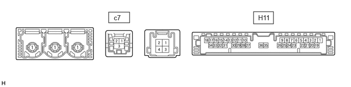
- DCM (TELEMATICS TRANSCEIVER)
Terminal No. (Symbol) Terminal Description Condition Specified Condition H11-1 (+B) - H11-20 (E) Power source (+B) Ignition switch off*1
Always*211 to 14 V H11-15 (USBV) - H11-20 (E) DCM (telematics transceiver) power supply signal Ignition switch ON 4.75 to 5.25 V Ignition switch off Below 1 V H11-17 (VOT+) - H11-20 (E) Sent voice signal Calling while using the operator service A waveform synchronized with the received voice is output H11-19 (IG2) - H11-20 (E) Power source (IG) Ignition switch ON 11 to 14 V Ignition switch off Below 1 V H11-20 (E) - Body ground Ground Always Below 1 Ω H11-25 (CANP) CAN communication signal - - H11-26 (CANN) CAN communication signal - - H11-31 (USBG) - Body ground Shield ground Always Below 1 Ω H11-33 (VOT-) - H11-20 (E) Sent voice signal Calling while using the operator service A waveform synchronized with the received voice is output c7-1 (US4+) USB communication line - - c7-2 (US4-) USB communication line - - c7-3 (UGD4) - Body ground Shield ground Always Below 1 V *1: for HV Model
*2: for Gasoline Model
- RADIO AND DISPLAY RECEIVER ASSEMBLY
Refer to TERMINALS OF ECU [10/2022 - ]