DTC B1571-11: Indicator (Green) Circuit Short to Ground; DTC B1571-13: Indicator (Green) Circuit Open [12/2019 - ]: Procedure
- CHECK DTC
- Turn the ignition switch off.
- Connect the GTS to the DLC3.
- Turn the ignition switch to ON and wait for 10 seconds or more.
- Turn the GTS on.
- Clear the DTCs.
Body Electrical > Telematics > Clear DTCs
- Check for DTCs and check that no DTCs are output.
Body Electrical > Telematics > Trouble Codes
OK
No DTCs are output.
Result
Proceed to OK NG
Result:
OK
USE SIMULATION METHOD TO CHECK. Refer to HOW TO PROCEED WITH TROUBLESHOOTING [12/2019 - ]
Result:
NG
See step 2
- INSPECT MAP LIGHT ASSEMBLY (MANUAL (SOS) SWITCH) (GREEN INDICATOR)
- Remove the map light assembly (manual (SOS) switch).
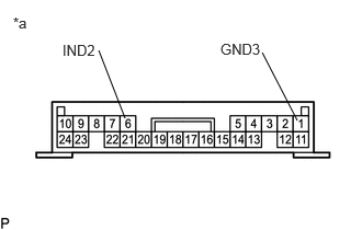
*a Component without harness connected
(Map Light Assembly (Manual (SOS) Switch))Refer to REMOVAL [12/2019 - ]
- Connect 2 dry-cell batteries (1.5 V each) in series.
- Connect a positive (+) lead from the batteries to terminal 6 (IND2) and a negative (-) lead to terminal 1 (GND3) of the map light assembly (manual (SOS) switch) connector.
- Check if the manual (SOS) switch green indicator comes on.
OK
Manual (SOS) switch green indicator illuminates.
Result
Proceed to OK NG
Result:
NG
REPLACE MAP LIGHT ASSEMBLY (MANUAL (SOS) SWITCH). Refer to REMOVAL [12/2019 - ]
Result:
OK
See step 3
- Remove the map light assembly (manual (SOS) switch).
- CHECK HARNESS AND CONNECTOR (DCM (TELEMATICS TRANSCEIVER) - MAP LIGHT ASSEMBLY (MANUAL (SOS) SWITCH))
- Disconnect the H11 DCM (telematics transceiver) connector.
- Disconnect the R11 map light assembly (manual (SOS) switch) connector.
- Measure the resistance according to the value(s) in the table below.
Standard Resistance
Tester Connection Condition Specified Condition H11-22 (IND2) - R11-6 (IND2) Always Below 1 Ω H11-22 (IND2) or R11-6 (IND2) - Body ground Always 10 kΩ or higher H11-3 (SIG-) - R11-1 (GND3) Always Below 1 Ω H11-3 (SIG-) or R11-1 (GND3) - Body ground Always 10 kΩ or higher Result
Proceed to OK NG
Result:
NG
REPAIR OR REPLACE HARNESS OR CONNECTOR
Result:
OK
See step 4
- REPLACE DCM (TELEMATICS TRANSCEIVER)
- Replace the DCM (telematics transceiver) with a new one.
Refer to REMOVAL [12/2019 - 10/2022] , or refer to REMOVAL [10/2022 - 11/2023] , or refer to REMOVAL [11/2023 - ]
NOTE:- The ignition switch must be off.
- Do not exchange the DCM (telematics transceiver) with one from another vehicle.
Result
Proceed to NEXT
Result:
NEXT
PERFORM DCM ACTIVATION. Refer to DCM ACTIVATION [12/2019 - ]
- Replace the DCM (telematics transceiver) with a new one.