DTC B1572-13: Microphone Circuit Open [12/2019 - 10/2022]: Procedure
- CHECK DTC
- Turn the ignition switch off.
- Connect the GTS to the DLC3.
- Turn the ignition switch to ON and wait for 10 seconds or more.
- Turn the GTS on.
- Clear the DTCs.
Body Electrical > Telematics > Clear DTCs
- Check for DTCs and check that no DTCs are output.
Body Electrical > Telematics > Trouble Codes
OK
No DTCs are output.
Result
Proceed to OK NG
Result:
OK
USE SIMULATION METHOD TO CHECK. Refer to HOW TO PROCEED WITH TROUBLESHOOTING [12/2019 - ]
Result:
NG
See step 2
- CHECK HARNESS AND CONNECTOR (DCM (TELEMATICS TRANSCEIVER) - MAP LIGHT ASSEMBLY)
- Disconnect the H11 DCM (telematics transceiver) connector.
- Disconnect the R12 map light assembly connector.
- Measure the resistance according to the value(s) in the table below.
Standard Resistance
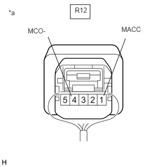
Tester Connection Condition Specified Condition H11-5 (MCVD) - R12-1 (MACC) Always Below 1 Ω H11-6 (MCI+) - R12-2 (MCO+) Always Below 1 Ω H11-7 (MCI-) - R12-4 (MCO-) Always Below 1 Ω H11-23 (SGND) - Body ground Always 10 kΩ or higher H11-5 (MCVD) or R12-1 (MACC) - Body ground Always 10 kΩ or higher H11-6 (MCI+) or R12-2 (MCO+) - Body ground Always 10 kΩ or higher H11-7 (MCI-) or R12-4 (MCO-) - Body ground Always 10 kΩ or higher Result
Proceed to OK NG
Result:
NG
REPAIR OR REPLACE HARNESS OR CONNECTOR
Result:
OK
See step 3
- CHECK DCM (TELEMATICS TRANSCEIVER) (TELEPHONE MICROPHONE ASSEMBLY POWER SOURCE)
- Remove the map light assembly but do not disconnect the connectors.
Refer to REMOVAL [12/2019 - 10/2022]
*a Component with harness connected
(Map Light Assembly) - Measure the voltage and resistance according to the value(s) in the table below.
Standard Voltage
Tester Connection Switch Condition Specified Condition R12-1 (MACC) - Body ground Ignition switch ON 4 to 6 V Standard Resistance
Tester Connection Condition Specified Condition R12-4 (MCO-) - Body ground Always Below 1 Ω Result
Proceed to OK NG
Result:
OK
REPLACE TELEPHONE MICROPHONE ASSEMBLY. Refer to REMOVAL [12/2019 - 10/2022]
Result:
NG
See step 4
- Remove the map light assembly but do not disconnect the connectors.
- REPLACE DCM (TELEMATICS TRANSCEIVER)
- Replace the DCM (telematics transceiver) with a new one.
Refer to REMOVAL [12/2019 - 10/2022]
NOTE:- The ignition switch must be off
- Do not exchange the DCM (telematics transceiver) with one from another vehicle.
Result
Proceed to NEXT
Result:
NEXT
PERFORM DCM ACTIVATION. Refer to DCM ACTIVATION [12/2019 - ]
- Replace the DCM (telematics transceiver) with a new one.