DTC B15CB-11: Telephone Main Antenna Circuit Short to Ground; DTC B15CB-13: Telephone Main Antenna Circuit Open [12/2019 - ]: Procedure
- CHECK DTC
- Turn the ignition switch off.
- Connect the GTS to the DLC3.
- Turn the ignition switch to ON and wait for 10 seconds or more.
- Turn the GTS on.
- Clear the DTCs.
Body Electrical > Telematics > Clear DTCs
- Check for DTCs and check that no DTCs are output.
Body Electrical > Telematics > Trouble Codes
OK
No DTCs are output.
Result
Proceed to OK NG
Result:
OK
USE SIMULATION METHOD TO CHECK
Refer to HOW TO PROCEED WITH TROUBLESHOOTING [12/2019 - ]
Result:
NG
See step 2
- INSPECT TELEPHONE AND GPS ANTENNA ASSEMBLY (FOR ROOF SIDE)
- Disconnect the telephone and GPS antenna assembly (for Roof Side) connector.
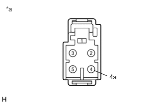
*a Component without harness connected
(Telephone and GPS Antenna Assembly (for Roof Side)) - Measure the resistance according to the value(s) in the table below.
Standard Resistance
Tester Connection Condition Specified Condition 4 - 4a Always 9 to 11 kΩ Result
Proceed to OK NG
Result:
NG
REPLACE TELEPHONE AND GPS ANTENNA ASSEMBLY (for Roof Side)
Refer to REMOVAL [12/2019 - ]
Result:
OK
See step 3
- Disconnect the telephone and GPS antenna assembly (for Roof Side) connector.
- INSPECT TELEPHONE AND GPS ANTENNA CORD (NO. 4 ANTENNA CORD SUB-ASSEMBLY)
- Disconnect the antenna connector from the telephone and GPS antenna (for Roof Side).
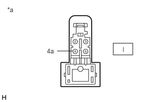
*a Component without harness connected (Telephone and GPS Antenna Cord (No. 4 Antenna Cord Sub-assembly)) - Disconnect the antenna connector from the telephone and GPS antenna cord (No. 3 antenna cord sub-assembly).
*a Component without harness connected (Telephone and GPS Antenna Cord (No. 4 Antenna Cord Sub-assembly)) - Measure the resistance according to the value(s) in the table below.
Standard Resistance
Tester Connection Condition Specified Condition I-4 - H-6 Always Below 1 Ω I-4a - H-6a Always Below 1 Ω I-4 or H-6 - Body ground Always 10 kΩ or higher Result
Proceed to OK NG
Result:
NG
REPLACE TELEPHONE AND GPS ANTENNA CORD (NO. 4 ANTENNA CORD SUB-ASSEMBLY)
Refer to REMOVAL [12/2019 - 10/2022] , or refer to REMOVAL [10/2022 - 11/2023] , or refer to REMOVAL [11/2023 - 11/2024] , or refer to REMOVAL [11/2024 - ]
Result:
OK
See step 4
- Disconnect the antenna connector from the telephone and GPS antenna (for Roof Side).
- INSPECT TELEPHONE AND GPS ANTENNA CORD (NO. 3 ANTENNA CORD SUB-ASSEMBLY)
- Disconnect the antenna connector from the telephone and GPS antenna cord (No. 4 antenna cord sub-assembly).
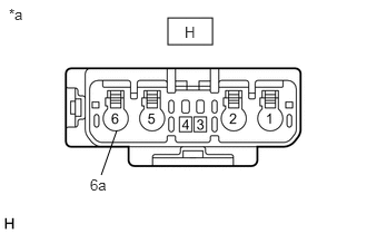
*a Component without harness connected (Telephone and GPS Antenna Cord (No. 3 Antenna Cord Sub-assembly)) - Disconnect the antenna connector from the telephone and GPS antenna cord (Antenna cord sub-assembly).
*a Component without harness connected (Telephone and GPS Antenna Cord (No. 3 Antenna Cord Sub-assembly)) - Measure the resistance according to the value(s) in the table below.
Standard Resistance
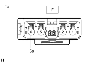
Tester Connection Condition Specified Condition G-6 - F-6 Always Below 1 Ω G-6a - F-6a Always Below 1 Ω G-6 or F-6 - Body ground Always 10 kΩ or higher Result
Proceed to OK NG
Result:
NG
REPLACE TELEPHONE AND GPS ANTENNA CORD (NO. 3 ANTENNA CORD SUB-ASSEMBLY)
Refer to REMOVAL [12/2019 - 10/2022] , or refer to REMOVAL [10/2022 - 11/2023] , or refer to REMOVAL [11/2023 - 11/2024] , or refer to REMOVAL [11/2024 - ]
Result:
OK
See step 5
- Disconnect the antenna connector from the telephone and GPS antenna cord (No. 4 antenna cord sub-assembly).
- INSPECT TELEPHONE AND GPS ANTENNA CORD (ANTENNA CORD SUB-ASSEMBLY)
- Disconnect the antenna connector from the telephone and GPS antenna cord (No. 3 antenna cord sub-assembly).
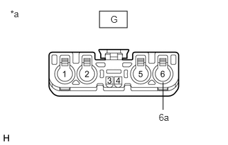
*a Component without harness connected
(Telephone and GPS Antenna Cord (Antenna Cord Sub-assembly)) - Disconnect the antenna connector from the DCM (telematics transceiver).
*a Component without harness connected
(Telephone and GPS Antenna Cord (Antenna Cord Sub-assembly)) - Measure the resistance according to the value(s) in the table below.
Standard Resistance
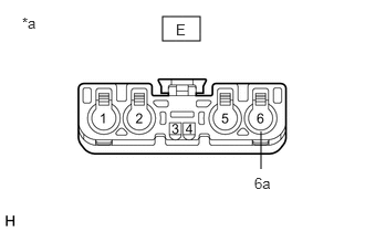
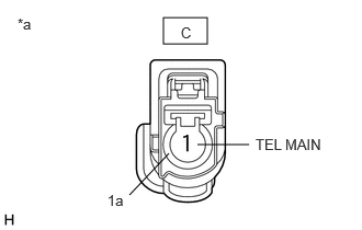
Tester Connection Condition Specified Condition E-6 - C-1 (TEL MAIN) Always Below 1 Ω E-6a - C-1a Always Below 1 Ω E-6 or C-1 (TEL MAIN) - Body ground Always 10 kΩ or higher Result
Proceed to OK NG
Result:
NG
REPLACE TELEPHONE AND GPS ANTENNA CORD (ANTENNA CORD SUB-ASSEMBLY)
Refer to REMOVAL [12/2019 - 10/2022] , or refer to REMOVAL [10/2022 - 11/2023] , or refer to REMOVAL [11/2023 - 11/2024] , or refer to REMOVAL [11/2024 - ]
Result:
OK
See step 6
- Disconnect the antenna connector from the telephone and GPS antenna cord (No. 3 antenna cord sub-assembly).
- REPLACE TELEPHONE AND GPS ANTENNA ASSEMBLY (FOR ROOF SIDE)
- Replace the telephone and GPS antenna assembly (for Roof Side) with a new or known good one and check if the same problem occurs again.
Refer to REMOVAL [12/2019 - ]
OK
The system returns to normal.
Result
Proceed to OK NG
Result:
OK
END
Result:
NG
See step 7
- Replace the telephone and GPS antenna assembly (for Roof Side) with a new or known good one and check if the same problem occurs again.
- REPLACE DCM (TELEMATICS TRANSCEIVER)
- Replace the DCM (Telematics Transceiver).
Refer to REMOVAL [12/2019 - 10/2022] , or refer to REMOVAL [10/2022 - 11/2023] , or refer to REMOVAL [11/2023 - ]
NOTE:- The ignition switch must be off.
- Do not swap the DCM (Telematics Transceiver) with one from another vehicle.
Result
Proceed to NEXT
Result:
NEXT
PERFORM DCM ACTIVATION
Refer to DCM ACTIVATION [12/2019 - ]
- Replace the DCM (Telematics Transceiver).