Emergency Call Switch Illumination Circuit [11/2023 - ]: Procedure
- CHECK HARNESS AND CONNECTOR (MAP LIGHT ASSEMBLY (MANUAL (SOS) SWITCH) POWER SOURCE)
- Disconnect the H11 DCM (telematics transceiver) connector.
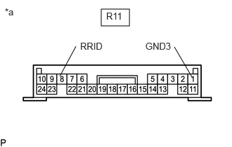
- Disconnect the R11 map light assembly (manual (SOS) switch) connector.
- Measure the voltage according to the value(s) in the table below.
Standard Voltage
Tester Connection Switch Condition Specified Condition R11-8 (RRID) - Body Ground Ignition switch ON 11 to 14 V - Measure the resistance according to the value(s) in the table below.
Standard Resistance
Tester Connection Condition Specified Condition H11-3 (SIG-) - R11-1 (GND3) Always Below 1 Ω H11-3 (SIG-) or R11-1 (GND3) - Body ground Always 10 kΩ or higher Result
Result Proceed to OK A NG B
Result:
B
REPAIR OR REPLACE HARNESS OR CONNECTOR
Result:
A
See step 2
- INSPECT MAP LIGHT ASSEMBLY (MANUAL (SOS) SWITCH)
- Remove the map light assembly (manual (SOS) switch).
Refer to REMOVAL [12/2019 - ]
*a Component without harness connected
(Map Light Assembly (Manual (SOS) Switch)) - Apply battery voltage to the connector and check that the map light assembly comes on.
OK
Measurement Condition Condition Specified Condition Battery positive (+) → R11-8 (RRID)
Battery negative (-) → R11-1 (GND3)Always Manual (SOS) switch illumination comes on Result
Proceed to OK NG
Result:
NG
REPLACE MAP LIGHT ASSEMBLY (MANUAL (SOS) SWITCH)
Refer to REMOVAL [12/2019 - ]
Result:
OK
See step 3
- Remove the map light assembly (manual (SOS) switch).
- REPLACE DCM (TELEMATICS TRANSCEIVER)
- Replace the DCM (telematics transceiver) with a new one.
Refer to REMOVAL [11/2023 - ]
NOTE:- The ignition switch must be off.
- Do not exchange the DCM (telematics transceiver) with one from another vehicle.
Result
Proceed to NEXT
Result:
NEXT
PERFORM DCM ACTIVATION
Refer to DCM ACTIVATION [12/2019 - ]
- Replace the DCM (telematics transceiver) with a new one.