Terminals Of Ecu [10/2022 - ]
HINT:
Check from the rear of the connector while it is connected to the components.
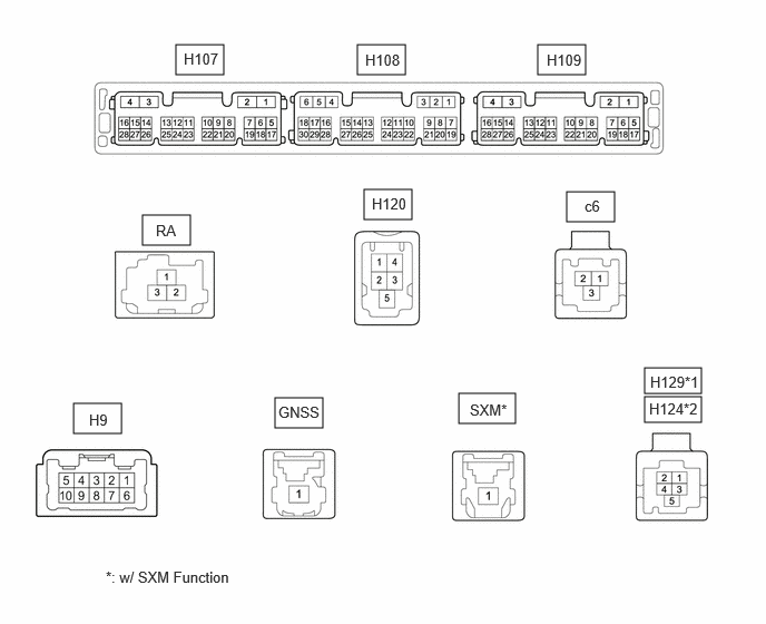
- RADIO AND DISPLAY RECEIVER ASSEMBLY
*1 w/ Parking Assist Monitor System *2 w/ Panoramic View Monitor System CONNECTOR H107Terminal No. (Symbol) Terminal Description Condition Specified Condition H107-1 (GND1) - Body ground Ground Always Below 1 Ω H107-4 (+B1) - H107-1 (GND1) Power source (+B) Ignition switch off 11 to 14 V H107-5 (REV) - H107-1 (GND1) Reverse Signal Ignition switch ON, shift position not in R → shift position in R 2 V or less → 11 to 14 V H107-7 (PKB) - H107-1 (GND1) Parking Brake Signal Ignition switch ON
Parking brake released → Ignition switch ON
Parking brake applied0.4 V or less → 3 V or higher H107-8 (SPD) - H107-1 (GND1) Vehicle speed signal Wheel being rotated Waveform 1 H107-12 (MUT1) - H107-1 (GND1)*1 Mute signal Audio system playing → Mute 3.5 V or higher → Below 1 V H107-15 (IG) - H107-1 (GND1) Power source (IG) Ignition switch ON 11 to 14 V H107-16 (ACC1) - H107-1 (GND1) Power source (ACC) Ignition switch ACC 11 to 14 V H107-17 (REVD) - H107-1 (GND1)*2 Camera image transition signal Normal → camera image screen change 2 V or less → 6 V or higher H107-18 (CSWA) - H107-1 (GND1)*3 Camera image transition signal Normal → camera image screen change 2 V or less → 6 V or higher H107-19 (CSW+) - H107-1 (GND1)*3 Camera image transition signal Normal → camera image screen change 2 V or less → 6 V or higher H107-20 (SWG) - H107-1 (GND1) Ground Always Below 1 Ω H107-21 (SW1) - H107-1 (GND1) Steering pad switch signal No switch pushed → Volume- switch pushed → Volume+ switch pushed → Seek- switch pushed → Seek+ switch pushed 2.7 V or higher → approximately 2.3 V → approximately 1.6 V → approximately 1.0 V → 0.8 V or less H107-22 (SW2) - H107-1 (GND1) Steering pad switch signal No switch pushed → Voice switch pushed → Off hook switch pushed → On hook switch pushed → MODE switch pushed 2.7 V or higher → approximately 2.3 V → approximately 1.6 V → approximately 1.0 V → 0.8 V or less H107-24 (ILL-) - H107-1 (GND1) Illumination signal ground Dimmed Pulse generation H107-25 (ILL+) - H107-1 (GND1) Illumination signal Light control switch not in tail or head position 11 to 14 V H107-26 (WK2) - H107-1 (GND1)*1 Stereo component amplifier assembly start up signal Ignition switch ACC 4 V or higher *1: w/ "JBL" Sound System
*2: w/ Parking Assist Monitor System
*3: w/ Panoramic View Monitor System
CONNECTOR H108Terminal No. (Symbol) Terminal Description Condition Specified Condition H108-1 (TX1+)*1 AVC-LAN communication signal - - H108-2 (TX1-)*1 AVC-LAN communication signal - - H108-4 (SGND) - H107-1 (GND1) Shield ground Always Below 1 Ω H108-5 (TMUT) - H107-1 (GND1)*2 Mute signal Normal → Emergency call mode 2.0 V or higher → Below 1 V H108-11 (CNH1) Local bus communication signal Service Menu - H108-12 (CNL1) Local bus communication signal Service Menu - H108-13 (CANH) CAN communication signal Service Menu - H108-14 (CANL) CAN communication signal Service Menu - H108-15 (VOR+)*2 Sound signal Answering incoming operator call A waveform synchronized with sound signals is output H108-16 (VOR-)*2 Sound signal Answering incoming operator call A waveform synchronized with sound signals is output H108-17 (USBG) - Body ground*2 Ground Always Below 1 Ω H108-18 (USBV) - H107-1 (GND1)*2 DCM (Telematics Transceiver) USB power source Ignition switch ON 3 V or higher H108-21 (MIN+) - H107-1 (GND1) Microphone voice signal Voice is being input A waveform synchronized with sound signals is output H108-22 (MIN-) - H107-1 (GND1) Microphone voice signal ground Always Below 1 Ω H108-23 (MACC) - Body ground*4 Microphone power source Ignition switch ON 7.5 to 8.5 V H108-24 (SGND) - Body ground Shield ground Always Below 1 Ω H108-25 (SNS) - H107-1 (GND1) Microphone circuit open detection signal Always Below 1 Ω H108-26 (CSLD) - H107-1 (GND1)*3 Shield ground Always Below 1 Ω H108-27 (CGND) - H107-1 (GND1)*3 Camera Ground Always Below 1 Ω H108-28 (V+) - H108-29 (V-)*3 Video Signal Ignition switch ON, shift position in R Waveform 2 H108-29 (V-) - H107-1 (GND1)*3 Video Signal Always Below 1 Ω H108-30 (CA+) - H107-1 (GND1)*3 Camera power source Ignition switch ON 7.5 to 9.0 V *1: w/ "JBL" Sound System
*2: w/ Telematics System
*3: for Rear View Monitor System
*4: w/o Telematics System
CONNECTOR H109Terminal No. (Symbol) Terminal Description Condition Specified Condition H109-4 (FBGN) - H107-1 (GND1)* Shield ground Always Below 1 Ω H109-15 (FB2+) - H107-1 (GND1)* Stereo component amplifier assembly voice signal 2 Voice is being input A waveform synchronized with sound signals is output H109-16 (FB2-) - H107-1 (GND1)* Stereo component amplifier assembly voice signal 2 Voice is being input A waveform synchronized with sound signals is output H109-17 (MI2+) - H107-1 (GND1) Microphone 2 voice signal Voice is being input A waveform synchronized with sound signals is output H109-18 (MI2-) - H107-1 (GND1) Microphone 2 voice signal ground Always Below 1 Ω H109-19 (SGD2) - H107-1 (GND1) Ground Always Below 1 Ω H109-20 (MAC2) - H107-1 (GND1) Microphone 2 power source Ignition switch ON 7.5 to 8.5 V H109-21 (SNS2) - H107-1 (GND1) Microphone 2 open circuit detection signal Always Below 1 Ω H109-27 (FB1+) - H107-1 (GND1)* Stereo component amplifier assembly voice signal 1 Voice is being input A waveform synchronized with sound signals is output H109-28 (FB1-) - H107-1 (GND1)* Stereo component amplifier assembly voice signal 1 Voice is being input A waveform synchronized with sound signals is output *: w/ "JBL" Sound System
CONNECTOR H9Terminal No. (Symbol) Terminal Description Condition Specified Condition H9-1 (FR+) - H107-1 (GND1) Sound signal Audio system playing A waveform synchronized with sound signals is output H9-2 (FL+) - H107-1 (GND1) Sound signal Audio system playing A waveform synchronized with sound signals is output H9-3 (RL+) - H107-1 (GND1) Sound signal*1
Interrupt sound signal*2Audio system playing*1
Interrupt sound signal being output*2A waveform synchronized with sound signals is output H9-4 (RR+) - H107-1 (GND1) Sound signal*1
Interrupt sound signal*2Audio system playing*1
Interrupt sound signal being output*2A waveform synchronized with sound signals is output H9-6 (FR-) - H107-1 (GND1) Sound signal Audio system playing A waveform synchronized with sound signals is output H9-7 (FL-) - H107-1 (GND1) Sound signal Audio system playing A waveform synchronized with sound signals is output H9-8 (RL-) - H107-1 (GND1) Sound signal*1
Interrupt sound signal*2Audio system playing*1
Interrupt sound signal being output*2A waveform synchronized with sound signals is output H9-9 (RR-) - H107-1 (GND1) Sound signal*1
Interrupt sound signal*2Audio system playing*1
Interrupt sound signal being output*2A waveform synchronized with sound signals is output *1: w/o "JBL" Sound System
*2: w/ "JBL" Sound System
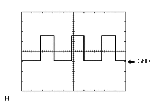
CONNECTOR C6Terminal No. (Symbol) Terminal Description Condition Specified Condition c6-1 (USB-) USB signal - - c6-2 (USB+) USB signal - - c6-3 (USBS) Shield ground Always Below 1 Ω CONNECTOR H120Terminal No. (Symbol) Terminal Description Condition Specified Condition H120-1 (USV1) Power source Ignition switch ON 4.75 to 5.25 V H120-2 (US1-) USB communication signal - - H120-3 (US1+) USB communication signal - - H120-4 (UGD1) Ground Always Below 1 Ω H120-5 (USG1) Shield ground Always Below 1 Ω CONNECTOR RATerminal No. (Symbol) Terminal Description Condition Specified Condition RA-1 (ANT+) Radio antenna power source Receiving radio broadcast 7 to 16 V RA-2a (GND) Ground - - RA-3 (MAIN) Radio signal - - RA-3a (GND) Ground - - CONNECTOR GNSSTerminal No. (Symbol) Terminal Description Condition Specified Condition GNSS-1 (GPS) GNSS signal - - CONNECTOR SXM (W/ SXM FUNCTION)Terminal No. (Symbol) Terminal Description Condition Specified Condition SXM-1 (XM) SXM Radio Signal - - CONNECTOR H124 (W/ PANORAMIC VIEW MONITOR SYSTEM)Terminal No. (Symbol) Terminal Description Condition Specified Condition H124-1 (GGND) Camera ground Always Below 1 Ω H124-2 (GB+) Camera power source Ignition switch ON 7.5 to 9.0 V H124-3 (GVO+) Video signal - - H124-4 (GVO-) Video signal - - H124-5 (SGND) Shield ground Always Below 1 Ω CONNECTOR H129 (W/ PARKING ASSIST MONITOR SYSTEM)Terminal No. (Symbol) Terminal Description Condition Specified Condition H129-1 (GGND) Camera ground Always Below 1 Ω H129-2 (GB+) Camera power source Ignition switch ON 7.5 to 9.0 V H129-3 (GVO+) Video signal - - H129-4 (GVO-) Video signal - - H129-5 (SGND) Shield ground Always Below 1 Ω - Waveform 1
Item Content Measurement terminal H107-8 (SPD) - H107-1 (GND1) Measurement setting 5 V/DIV., 20 ms/DIV Condition Wheel being rotated HINT:
The period changes depending on the rotation speed of the wheels.
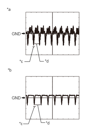
- Waveform 2
- Waveform A (camera lens not covered, displaying an image)
Item Content Measurement terminal H108-28 (V+) - H108-29 (V-) Measurement setting 200 mV/DIV., 50 μs/DIV. Condition Ignition switch ON, shift lever in R HINT:
- The video waveform changes according to the image sent by the rear television camera assembly.
- The video waveform is constantly output when the ignition switch ACC.
*a Waveform A (camera lens not covered, displaying an image) *b Waveform B (camera lens covered, blacking out the screen) *c Synchronization Signal *d Video Waveform - Waveform B (camera lens covered, blacking out the screen)
Item Content Measurement terminal H108-28 (V+) - H108-29 (V-) Measurement setting 200 mV/DIV., 50 μs/DIV. Condition Ignition switch ON, shift lever in R HINT:
- The video waveform changes according to the image sent by the rear television camera assembly.
- The video waveform is constantly output when the ignition switch ACC.
- Waveform A (camera lens not covered, displaying an image)
- Waveform 1
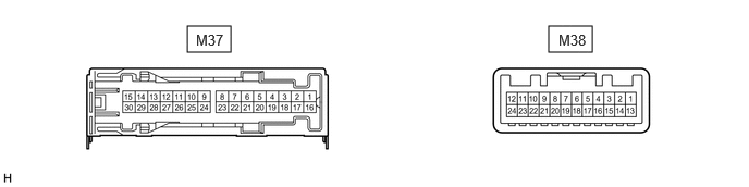
- STEREO COMPONENT AMPLIFIER ASSEMBLY (w/ "JBL" Sound System) CONNECTOR M37
Terminal No. (Symbol) Terminal Description Condition Specified Condition M37-1 (+B) - M37-3 (GND) Power source (+B) Ignition switch off 11 to 14 V M37-3 (GND) - Body ground Ground Always Below 1 Ω M37-5 (WF2+) - M37-3 (GND) Sound signal (Woofer) Audio system playing A waveform synchronized with sound signals is output M37-6 (WF1+) - M37-3 (GND) Sound signal (Woofer) Audio system playing A waveform synchronized with sound signals is output M37-8 (TWL+) - M37-3 (GND) Front sound signal (LH) Audio system playing A waveform synchronized with sound signals is output M37-9 (TWR+) - M37-3 (GND) Front sound signal (RH) Audio system playing A waveform synchronized with sound signals is output M37-10 (SL+) - M37-3 (GND) Rear sound signal (LH) Audio system playing A waveform synchronized with sound signals is output M37-11 (SR+) - M37-3 (GND) Rear sound signal (RH) Audio system playing A waveform synchronized with sound signals is output M37-12 (FL+) - M37-3 (GND) Front sound signal (LH) Audio system playing A waveform synchronized with sound signals is output M37-13 (FR+) - M37-3 (GND) Front sound signal (RH) Audio system playing A waveform synchronized with sound signals is output M37-14 (RL+) - M37-3 (GND) Rear sound signal (LH) Audio system playing A waveform synchronized with sound signals is output M37-15 (RR+) - M37-3 (GND) Rear sound signal (RH) Audio system playing A waveform synchronized with sound signals is output M37-16 (+B2) - M37-3 (GND) Power source (+B) Ignition switch off 11 to 14 V M37-18 (GND2) - Body ground Ground Always Below 1 Ω M37-20 (WF2-) - M37-3 (GND) Sound signal (Woofer) Audio system playing A waveform synchronized with sound signals is output M37-21 (WF1-) - M37-3 (GND) Sound signal (Woofer) Audio system playing A waveform synchronized with sound signals is output M37-23 (TWL-) - M37-3 (GND) Front sound signal (LH) Audio system playing A waveform synchronized with sound signals is output M37-24 (TWR-) - M37-3 (GND) Front sound signal (RH) Audio system playing A waveform synchronized with sound signals is output M37-25 (SL-) - M37-3 (GND) Rear sound signal (LH) Audio system playing A waveform synchronized with sound signals is output M37-26 (SR-) - M37-3 (GND) Rear sound signal (RH) Audio system playing A waveform synchronized with sound signals is output M37-27 (FL-) - M37-3 (GND) Front sound signal (LH) Audio system playing A waveform synchronized with sound signals is output M37-28 (FR-) - M37-3 (GND) Front sound signal (RH) Audio system playing A waveform synchronized with sound signals is output M37-29 (RL-) - M37-3 (GND) Rear sound signal (LH) Audio system playing A waveform synchronized with sound signals is output M37-30 (RR-) - M37-3 (GND) Rear sound signal (RH) Audio system playing A waveform synchronized with sound signals is output CONNECTOR M38Terminal No. (Symbol) Terminal Description Condition Specified Condition M38-1 (MUTE) - M37-3 (GND) Mute signal Normal → Mute 3.5 V or higher → Below 1 V M38-2 (L-) - M37-3 (GND) Input voice signal (LH) Voice is being input A waveform synchronized with sound signals is output M38-3 (L+) - M37-3 (GND) Input voice signal (LH) Voice is being input A waveform synchronized with sound signals is output M38-4 (R-) - M37-3 (GND) Input voice signal (RH) Voice is being input A waveform synchronized with sound signals is output M38-5 (R+) - M37-3 (GND) Input voice signal (RH) Voice is being input A waveform synchronized with sound signals is output M38-6 (SLD) - Body ground Shield ground Always Below 1 Ω M38-7 (TX-) AVC-LAN communication signal Service Menu - M38-8 (TX+) AVC-LAN communication signal Service Menu - M38-9 (FB1-) - M37-3 (GND) Sound signal Audio system playing A waveform synchronized with sound signals is output M38-10 (FB1+) - M37-3 (GND) Sound signal Audio system playing A waveform synchronized with sound signals is output M38-11 (SPD) - M37-3 (GND) Vehicle speed signal Wheel being rotated Waveform 1 M38-12 (WK2) - M37-3 (GND) Stereo component amplifier assembly start signal Ignition switch ACC 4 V or higher M38-13 (SLD1) - Body ground Ground Always Below 1 Ω M38-14 (ll1-) - M37-3 (GND) Input voice signal (LH) Interrupt voice is being input A waveform synchronized with sound signals is output M38-15 (ll1+) - M37-3 (GND) Input voice signal (LH) Interrupt voice is being input A waveform synchronized with sound signals is output M38-16 (ll2-) - M37-3 (GND) Input voice signal (RH) Interrupt voice is being input A waveform synchronized with sound signals is output M38-17 (ll2+) - M37-3 (GND) Input voice signal (RH) Interrupt voice is being input A waveform synchronized with sound signals is output M38-18 (SLD2) - Body ground Shield ground Always Below 1 Ω M38-21 (FB2-) - M37-3 (GND) Sound signal Audio system playing A waveform synchronized with sound signals is output M38-22 (FB2+) - M37-3 (GND) Sound signal Audio system playing A waveform synchronized with sound signals is output M38-24 (TMUT) - M37-3 (GND) Mute signal Normal → Mute 3.5 V or higher → Below 1 V - DCM (TELEMATICS TRANSCEIVER) (w/ Telematics System)
HINT:
Refer to TERMINALS OF ECU [10/2022 - ]
- COMBINATION METER ASSEMBLY
HINT:
except 12.3 Inch Display: Refer to TERMINALS OF ECU [12/2019 - 11/2023] , or refer to TERMINALS OF ECU [11/2023 - ]
for 12.3 Inch Display: Refer to HOW TO PROCEED WITH TROUBLESHOOTING [10/2022 - ]
- MOBILE WIRELESS CHARGER CRADLE ASSEMBL (w/ Wireless Charging System)
HINT:
Refer to TERMINALS OF ECU [10/2022 - 11/2023] , or refer to TERMINALS OF ECU [11/2023 - ]
- REAR TELEVISION CAMERA ASSEMBLY (w/ Parking Assist Monitor System)
HINT:
Refer to TERMINALS OF ECU [10/2022 - ]
- PARKING ASSIST ECU (w/ Panoramic View Monitor System)
HINT:
Refer to TERMINALS OF ECU [10/2022 - ]
- HEADUP DISPLAY (METER MIRROR SUB-ASSEMBLY) (w/ Headup Display System)
HINT:
Refer to TERMINALS OF ECU [12/2019 - ]