Terminals Of Ecu [12/2019 - 10/2022]
HINT:
Check from the rear of the connector while it is connected to the components.
- TELEVISION DISPLAY ASSEMBLY
Terminal No. (Symbol) Terminal Description Condition Specification R16-1 (+B) - R16-17 (GND) Power source (+B) Always*3
Ignition switch off*411 to 14 V*5
10.5 to 16 V*6R16-2 (ACC) - R16-17 (GND) Power source (ACC) Ignition switch ACC 11 to 14 V*5
10.5 to 16 V*6R16-4 (TX1+) AVC-LAN communication signal - - R16-5 (TX1-) AVC-LAN communication signal - - R16-6 (MUT1) - R16-17 (GND)*1 Mute signal Ignition switch ACC
RSE system playing
→ Changing source3.5 V or higher
→ Below 1 VR16-7 (L1+) - R16-17 (GND)*1 Sound signal (Left) RSE system playing A waveform synchronized with sound signals is output R16-7 (L1+) - R16-8 (SGN7)*2 Sound signal (Left) RSE system playing A waveform synchronized with sound signals is output R16-8 (L1-) - R16-17 (GND)*1 Sound signal (Left) RSE system playing A waveform synchronized with sound signals is output R16-8 (SGN7) - R16-17 (GND)*2 Sound signal ground Always Below 1 V R16-9 (R1+) - R16-17 (GND)*1 Sound signal (Right) RSE system playing A waveform synchronized with sound signals is output R16-9 (R1+) - R16-8 (SGN7)*2 Sound signal (Right) RSE system playing A waveform synchronized with sound signals is output R16-10 (R1-) - R16-17 (GND)*1 Sound signal (Right) RSE system playing A waveform synchronized with sound signals is output R16-11 (AGND) - Body ground Shield ground Always Below 1 V R16-15 (ILL+) - R16-17 (GND) Illumination signal Light control switch off Below 1 V Ignition switch off
Light control switch in tail or head position11 to 14 V R16-16 (ILL-) - R16-17 (GND) Illumination signal Light control switch off Below 1 V Ignition switch off
Light control switch in tail or head positionPulse generation R16-17 (GND) - Body ground Ground Always Below 1 V *1: for 8 Inch Display
*2: for 12.3 Inch Display
*3: for Gasoline Model
*4: for HV Model
*5: w/o Stop and Start System
*6: w/ Stop and Start System
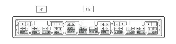
- RADIO AND DISPLAY RECEIVER ASSEMBLY (for 8 Inch Display)
Terminal No. (Symbol) Terminal Description Condition Specification H1-1 (GND1) - Body ground Ground Always Below 1 V H1-19 (TX+) AVC-LAN communication signal - - H1-20 (TX-) AVC-LAN communication signal - - H2-7 (CDL+) - H1-1 (GND1) Sound signal (Left) RSE system playing A waveform synchronized with sound signals is output H2-8 (CDL-) - H1-1 (GND1) Sound signal (Left) RSE system playing A waveform synchronized with sound signals is output H2-9 (CDR+) - H1-1 (GND1) Sound signal (Right) RSE system playing A waveform synchronized with sound signals is output H2-10 (CDR-) - H1-1 (GND1) Sound signal (Right) RSE system playing A waveform synchronized with sound signals is output H2-12 (MUTE) - H1-1 (GND1) Mute signal Ignition switch ACC
RSE system playing
→ Changing source3.5 V or higher
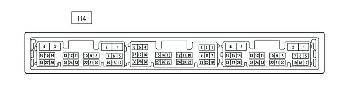
→ Below 1 V - RADIO RECEIVER ASSEMBLY (for 12.3 Inch Display)
Terminal No. (Symbol) Terminal Description Condition Specification H4-1 (GND1) - Body ground Ground Always Below 1 V H4-10 (AGND) - Body ground Shield ground Always Below 1 V H4-11 (VAL+) - H4-13 (VA-) Sound signal (Left) RSE system playing A waveform synchronized with sound signals is output H4-12 (VAR+) - H4-13 (VA-) Sound signal (Right) RSE system playing A waveform synchronized with sound signals is output H4-13 (VA-) - H4-1 (GND1) Sound signal ground Always Below 1 V H4-19 (TX+) AVC-LAN communication signal - - H4-20 (TX-) AVC-LAN communication signal - -