Rear Television Camera Communication Stop Mode [12/2019 - 10/2022]: Procedure
- CHECK FOR OPEN IN CAN BUS LINES (REAR TELEVISION CAMERA ASSEMBLY BRANCH LINE)
- Disconnect the cable from the negative (-) battery terminal.
- Disconnect the W15 rear television camera assembly connector.
- Measure the resistance according to the value(s) in the table below.
Standard Resistance
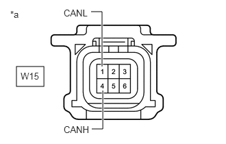
Tester Connection Condition Specified Condition W15-4 (CANH) - W15-1 (CANL) Cable disconnected from negative (-) battery terminal 54 to 69 Ω *a Front view of wire harness connector
(to Rear Television Camera Assembly)Result
Result OK NG
Result:
NG
REPAIR OR REPLACE CAN BRANCH LINES OR CONNECTOR (REAR TELEVISION CAMERA ASSEMBLY)
Result:
OK
See step 2
- CHECK VEHICLE TYPE
- Check vehicle type.
Result
Result Proceed to w/ Parking Assist Monitor System A w/ Panoramic View Monitor System B
Result:
B
See step 5
Result:
A
See step 3
- Check vehicle type.
- CHECK HARNESS AND CONNECTOR (POWER SOURCE CIRCUIT)
- Measure the resistance according to the value(s) in the table below.
Standard Resistance
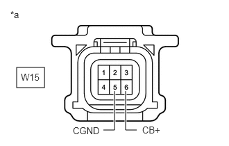
Tester Connection Condition Specified Condition W15-5 (CGND) - Body ground Cable disconnected from negative (-) battery terminal Below 1 Ω *a Front view of wire harness connector
(to Rear Television Camera Assembly) - Reconnect the cable to the negative (-) battery terminal.
- Measure the voltage according to the value(s) in the table below.
Standard Voltage
Tester Connection Condition Specified Condition W15-6 (CB+) - Body ground Ignition switch ACC 5.5 to 7.05 V Result
Result OK NG
Result:
OK
REPLACE REAR TELEVISION CAMERA ASSEMBLY
Refer to REMOVAL [12/2019 - 11/2023]
Result:
NG
See step 4
- Measure the resistance according to the value(s) in the table below.
- CHECK HARNESS AND CONNECTOR (REAR TELEVISION CAMERA ASSEMBLY - RADIO AND DISPLAY RECEIVER ASSEMBLY)
Refer to DTC C1622: Back Camera Disconnected [12/2019 - 10/2022]
Result
Result OK NG Result:
OK
REPLACE RADIO AND DISPLAY RECEIVER ASSEMBLY
Refer to REMOVAL [12/2019 - 10/2022]
Result:
NG
REPAIR OR REPLACE HARNESS OR CONNECTOR (POWER SOURCE CIRCUIT)
- CHECK HARNESS AND CONNECTOR (POWER SOURCE CIRCUIT)
- Measure the resistance according to the value(s) in the table below.
Standard Resistance
Tester Connection Condition Specified Condition W15-5 (CGND) - Body ground Cable disconnected from negative (-) battery terminal Below 1 Ω *a Front view of wire harness connector
(to Rear Television Camera Assembly) - Reconnect the cable to the negative (-) battery terminal.
- Measure the voltage according to the value(s) in the table below.
Standard Voltage
Tester Connection Condition Specified Condition W15-6 (CB+) - Body ground Ignition switch ACC 5.5 to 7.05 V Result
Result OK NG
Result:
OK
REPLACE REAR TELEVISION CAMERA ASSEMBLY
Refer to REMOVAL [12/2019 - 11/2023]
Result:
NG
See step 6
- Measure the resistance according to the value(s) in the table below.
- CHECK HARNESS AND CONNECTOR (REAR TELEVISION CAMERA ASSEMBLY - PARKING ASSIST ECU)
Refer to DTC C1622: Open or Short Circuit in Back Camera Signal [12/2019 - 10/2022]
Result
Result OK NG Result:
OK
REPLACE PARKING ASSIST ECU
Refer to REMOVAL [12/2019 - 10/2022]
Result:
NG
REPAIR OR REPLACE HARNESS OR CONNECTOR (POWER SOURCE CIRCUIT)