Terminals Of Ecu [12/2019 - 10/2021]
- After turning the ignition switch off, waiting time may be required before disconnecting the cable from the negative (-) auxiliary battery terminal. Therefore, make sure to read the disconnecting the cable from the negative (-) auxiliary battery terminal notices before proceeding with work.
Refer to INITIALIZATION [12/2019 - 09/2020] , or refer to INITIALIZATION [09/2020 - 10/2021]
- Before measuring the resistance of the CAN bus, turn the ignition switch off and leave the vehicle for 1 minute or more without operating the key or any switches, or opening or closing the doors. After that, disconnect the cable from the negative (-) auxiliary battery terminal and leave the vehicle for 10 minutes or more before measuring the resistance.
- This section describes the standard values for all CAN related components.
HINT:
- The systems (ECUs and sensors) that use CAN communication vary depending on the vehicle and optional equipment. Check which systems (ECUs and sensors) are installed to the vehicle.
Refer to SYSTEM DIAGRAM [12/2019 - 10/2021]
- Operating the ignition switch, any other switches or a door triggers related ECU and sensor communication on the CAN. This communication will cause the resistance value to change.
- Even after DTCs are cleared, if a DTC is stored again after driving the vehicle for a while, the malfunction may be occurring due to vibration of the vehicle. In such a case, wiggling the ECUs or wire harness while performing the inspection below may help determine the cause of the malfunction.
- NO. 1 GLOBAL CAN JUNCTION CONNECTOR
- Check the No. 1 global CAN junction connector.
- Connection diagram
*a Front view of wire harness connector
(to No. 1 Global CAN Junction Connector)- - - Check the connection diagram of the components which are connected to the No. 1 global CAN junction connector.
Terminal No. (Symbol) Wiring Color Connected to A77-1 (CANH) G No. 2 skid control ECU (brake actuator assembly)
(for Bus 2)A77-12 (CANL) W A77-2 (CANH) R No. 1 skid control ECU (brake booster with master cylinder assembly)
(for Bus 2)A77-13 (CANL) W A77-6 (CANH) SB Central gateway ECU (network gateway ECU)
(for Bus 2)A77-17 (CANL) W A77-7 (CANH) P Vehicle approaching speaker controller
(for Bus 2)A77-18 (CANL) W A77-8 (CANH) L Hybrid vehicle control ECU
(for Bus 2)A77-19 (CANL) W A77-9 (CANH) B ECM
(for Bus 2)A77-20 (CANL) W A77-10 (CANH) LG Inverter with converter assembly*
(for Bus 2)A77-21 (CANL) W A77-11 (CANH) V Inverter with converter assembly
(for Bus 2)A77-22 (CANL) W - *: for AWD
- Connection diagram
- Check the No. 1 global CAN junction connector.
- NO. 2 GLOBAL CAN JUNCTION CONNECTOR
- Check the No. 2 global CAN junction connector.
- Connection diagram
*a Front view of wire harness connector
(to No. 2 Global CAN Junction Connector)- - - Check the connection diagram of the components which are connected to the No. 2 global CAN junction connector.
Terminal No. (Symbol) Wiring Color Connected to H90-2 (CANH) G Rack and pinion power steering gear assembly
(for Bus 4)H90-12 (CANL) W H90-3 (CANH) L No. 1 skid control ECU (brake booster with master cylinder assembly)
(for Bus 4)H90-13 (CANL) W H90-4 (CANH) P ECM
(for Bus 4)H90-14 (CANL) W H90-5 (CANH) BE Hybrid vehicle control ECU
(for Bus 4)H90-15 (CANL) W H90-6 (CANH) SB No. 8 global CAN junction connector
(for Bus 4)H90-16 (CANL) W H90-7 (CANH) V Steering sensor
(for Bus 4)H90-17 (CANL) W H90-8 (CANH) R Airbag sensor assembly
(for Bus 4)H90-18 (CANL) W H90-9 (CANH) P Tire pressure warning ECU and receiver
(for Bus 4)H90-19 (CANL) W
- Connection diagram
- Check the No. 2 global CAN junction connector.
- NO. 3 GLOBAL CAN JUNCTION CONNECTOR
- Check the No. 3 global CAN junction connector.
- Connection diagram
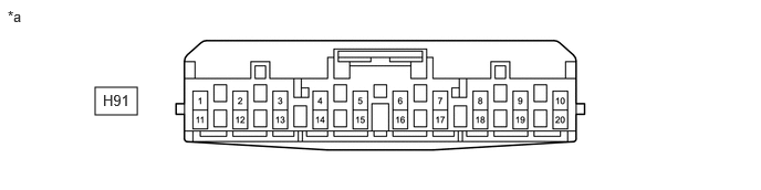
*a Front view of wire harness connector
(to No. 3 Global CAN Junction Connector)- - - Check the connection diagram of the components which are connected to the No. 3 global CAN junction connector.
Terminal No. (Symbol) Wiring Color Connected to H91-1 (CANH) L Headlight ECU sub-assembly RH*1
(for Bus 5)H91-11 (CANL) W H91-2 (CANH) LG Central gateway ECU (network gateway ECU)
(for Bus 5)H91-12 (CANL) W H91-3 (CANH) G Certification ECU (smart key ECU assembly)
(for Bus 5)H91-13 (CANL) W H91-4 (CANH) SB Air conditioning amplifier assembly
(for Bus 5)H91-14 (CANL) W H91-5 (CANH) P Outer mirror control ECU assembly RH*2
(for Bus 5)H91-15 (CANL) W H91-6 (CANH) B No. 4 global CAN junction connector
(for Bus 5)H91-16 (CANL) W H91-7 (CANH) GR Integration control sub-assembly*3
(for Bus 5)H91-17 (CANL) W - *1: w/ AFS
- *2: w/ Seat Position Memory System
- *3: w/ Toyota Multi Operation Touch System
- Connection diagram
- Check the No. 3 global CAN junction connector.
- NO. 4 GLOBAL CAN JUNCTION CONNECTOR
- Check the No. 4 global CAN junction connector.
- Connection diagram
*a Front view of wire harness connector
(to No. 4 Global CAN Junction Connector)- - - Check the connection diagram of the components which are connected to the No. 4 global CAN junction connector.
Terminal No. (Symbol) Wiring Color Connected to H92-1 (CANH) BE Main body ECU (multiplex network body ECU)
(for Bus 5)H92-7 (CANL) W H92-2 (CANH) LG Meter mirror sub-assembly*1
(for Bus 5)H92-8 (CANL) W H92-3 (CANH) B No. 3 global CAN junction connector
(for Bus 5)H92-9 (CANL) W H92-4 (CANH) R No. 9 global CAN junction connector
(for Bus 5)H92-10 (CANL) W H92-5 (CANH) P Outer mirror control ECU assembly LH*2
(for Bus 5)H92-11 (CANL) W H92-6 (CANH) L Headlight ECU sub-assembly LH*3
(for Bus 5)H92-12 (CANL) W - *1: w/ Headup Display System
- *2: w/ Seat Position Memory System
- *3: w/ AFS
- Connection diagram
- Check the No. 4 global CAN junction connector.
- NO. 5 GLOBAL CAN JUNCTION CONNECTOR
- Check the No. 5 global CAN junction connector.
- Connection diagram
*a Front view of wire harness connector
(to No. 5 Global CAN Junction Connector)- - - Check the connection diagram of the components which are connected to the No. 5 global CAN junction connector.
Terminal No. (Symbol) Wiring Color Connected to H94-1 (CANH) P Central gateway ECU (network gateway ECU)
(for Bus 1)H94-11 (CANL) W H94-2 (CANH) R Millimeter wave radar sensor assembly
(for Bus 1)H94-12 (CANL) W H94-3 (CANH) L Forward recognition camera
(for Bus 1)H94-13 (CANL) W H94-4 (CANH) B No. 10 global CAN junction connector
(for Bus 1)H94-14 (CANL) W H94-5 (CANH) L Clearance warning ECU assembly*1
(for Bus 1)H94-15 (CANL) W H94-6 (CANH) GR Parking assist ECU*2
(for Bus 1)H94-16 (CANL) W H94-7 (CANH) G Swing grille actuator assembly
(for Bus 1)H94-17 (CANL) W - *1: w/ Intuitive Parking Assist System
- *2: w/ Panoramic View Monitor System
- Connection diagram
- Check the No. 5 global CAN junction connector.
- NO. 7 GLOBAL CAN JUNCTION CONNECTOR
- Check the No. 7 global CAN junction connector.
- Connection diagram
*a Front view of wire harness connector
(to No. 7 Global CAN Junction Connector)- - - Check the connection diagram of the components which are connected to the No. 7 global CAN junction connector.
Terminal No. (Symbol) Wiring Color Connected to H99-2 (CANH) B Central gateway ECU (network gateway ECU)
(for Bus 3)H99-13 (CANL) W H99-3 (CANH) G Central gateway ECU (network gateway ECU)
(for Bus 3)H99-14 (CANL) W H99-4 (CANH) B Radio and display receiver assembly*1
(for Bus 3)H99-15 (CANL) W H99-4 (CANH) B Radio receiver assembly*2
(for Bus 3)H99-15 (CANL) W H99-5 (CANH) R DCM (telematics transceiver)*3
(for Bus 3)H99-16 (CANL) W - *1: for 8 Inch Display
- *2: for 12.3 Inch Display
- *3: w/ Telematics Transceiver
- Connection diagram
- Check the No. 7 global CAN junction connector.
- NO. 8 GLOBAL CAN JUNCTION CONNECTOR
- Check the No. 8 global CAN junction connector.
- Connection diagram
*a Front view of wire harness connector
(to No. 8 Global CAN Junction Connector)- - - Check the connection diagram of the components which are connected to the No. 8 global CAN junction connector.
Terminal No. (Symbol) Wiring Color Connected to M33-2 (CANH) LG No. 2 skid control ECU (brake actuator assembly)
(for Bus 4)M33-8 (CANL) W M33-3 (CANH) G Central gateway ECU (network gateway ECU)
(for Bus 4)M33-9 (CANL) W M33-4 (CANH) SB No. 2 global CAN junction connector
(for Bus 4)M33-10 (CANL) W M33-5 (CANH) GR Occupant detection ECU
(for Bus 4)M33-11 (CANL) W M33-6 (CANH) R Yaw rate sensor
(for Bus 4)M33-12 (CANL) W
- Connection diagram
- Check the No. 8 global CAN junction connector.
- NO. 9 GLOBAL CAN JUNCTION CONNECTOR
- Check the No. 9 global CAN junction connector.
- Connection diagram
*a Front view of wire harness connector
(to No. 9 Global CAN Junction Connector)- - - Check the connection diagram of the components which are connected to the No. 9 global CAN junction connector.
Terminal No. (Symbol) Wiring Color Connected to M96-1 (CANH) LG Multiplex network door ECU
(for Bus 5)M96-7 (CANL) W M96-2 (CANH) G Position control ECU assembly LH*
(for Bus 5)M96-8 (CANL) W M96-3 (CANH) R No. 4 global CAN junction connector
(for Bus 5)M96-9 (CANL) W M96-4 (CANH) B Combination meter assembly
(for Bus 5)M96-10 (CANL) W - *: w/ Seat Position Memory System
- Connection diagram
- Check the No. 9 global CAN junction connector.
- NO. 10 GLOBAL CAN JUNCTION CONNECTOR
- Check the No. 10 global CAN junction connector.
- Connection diagram
*a Front view of wire harness connector
(to No. 10 Global CAN Junction Connector)- - - Check the connection diagram of the components which are connected to the No. 10 global CAN junction connector.
Terminal No. (Symbol) Wiring Color Connected to M97-3 (CANH) V Blind spot monitor sensor LH
(for Bus 1)M97-9 (CANL) W M97-4 (CANH) B No. 1 CAN junction terminal
(for Bus 1)M97-10 (CANL) W M97-5 (CANH) R Rear television camera assembly*
(for Bus 1)M97-11 (CANL) W M97-6 (CANH) B No. 5 global CAN junction connector
(for Bus 1)M97-12 (CANL) W - *: w/ Parking Assist Monitor System or Panoramic View Monitor System
- Connection diagram
- Check the No. 10 global CAN junction connector.
- NO. 1 CAN JUNCTION TERMINAL
- Check the No. 1 CAN junction terminal.
- Connection diagram
*a Front view of wire harness connector
(to No. 1 CAN Junction Terminal)- - - Check the connection diagram of the components which are connected to the No. 1 CAN junction terminal.
Terminal No. (Symbol) Wiring Color Connected to M89-3 (CANH) B No. 10 global CAN junction connector
(for Bus 1)M89-2 (CANL) W
- Connection diagram
- Check the No. 1 CAN junction terminal.
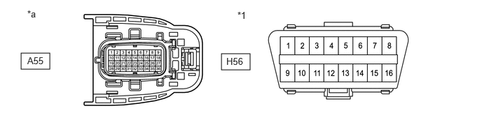
- DLC3
- Disconnect the cable from the negative (-) auxiliary battery terminal.
- Measure the resistance according to the value(s) in the table below.
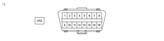
*1 DLC3 - - Standard Resistance
Terminal No. (Symbol) Terminal Description Condition Specified Condition H56-6 (CANH) - H56-14 (CANL) HIGH-level CAN bus line - LOW-level CAN bus line Cable disconnected from negative (-) auxiliary battery terminal 54 to 69 Ω H56-6 (CANH) - H56-4 (CG) HIGH-level CAN bus line - Ground Cable disconnected from negative (-) auxiliary battery terminal 200 Ω or higher H56-14 (CANL) - H56-4 (CG) LOW-level CAN bus line - Ground Cable disconnected from negative (-) auxiliary battery terminal 200 Ω or higher H56-6 (CANH) - H56-16 (BAT) HIGH-level CAN bus line - Auxiliary battery positive (+) Cable disconnected from negative (-) auxiliary battery terminal 6 kΩ or higher H56-14 (CANL) - H56-16 (BAT) LOW-level CAN bus line - Auxiliary battery positive (+) Cable disconnected from negative (-) auxiliary battery terminal 6 kΩ or higher
- CENTRAL GATEWAY ECU (NETWORK GATEWAY ECU)
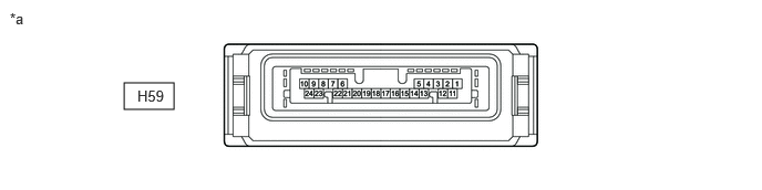
*a Component without harness connected
(Central Gateway ECU (Network Gateway ECU))- - - Disconnect the cable from the negative (-) auxiliary battery terminal.
- Disconnect the H59 central gateway ECU (network gateway ECU) connector.
- Measure the resistance according to the value(s) in the table below.
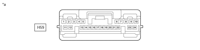
*a Front view of wire harness connector
(to Central Gateway ECU (Network Gateway ECU))- - Standard Resistance
DIAGNOSIS BUS BRANCH LINES (DLC3 - CENTRAL GATEWAY ECU (NETWORK GATEWAY ECU))Terminal No. (Symbol) Terminal Description Condition Specified Condition H59-14 (CA6H) - H59-5 (CA6L) HIGH-level CAN bus line - LOW-level CAN bus line Cable disconnected from negative (-) auxiliary battery terminal 1 MΩ or higher H59-14 (CA6H) - H59-10 (GND) HIGH-level CAN bus line - Ground Cable disconnected from negative (-) auxiliary battery terminal 200 Ω or higher H59-5 (CA6L) - H59-10 (GND) LOW-level CAN bus line - Ground Cable disconnected from negative (-) auxiliary battery terminal 200 Ω or higher H59-14 (CA6H) - H59-1 (BATT) HIGH-level CAN bus line - Auxiliary battery positive (+) Cable disconnected from negative (-) auxiliary battery terminal 6 kΩ or higher H59-5 (CA6L) - H59-1 (BATT) LOW-level CAN bus line - Auxiliary battery positive (+) Cable disconnected from negative (-) auxiliary battery terminal 6 kΩ or higher BUS 1 MAIN LINESTerminal No. (Symbol) Terminal Description Condition Specified Condition H59-23 (CA1H) - H59-8 (CA1L) HIGH-level CAN bus line - LOW-level CAN bus line Cable disconnected from negative (-) auxiliary battery terminal 108 to 132 Ω H59-23 (CA1H) - H59-10 (GND) HIGH-level CAN bus line - Ground Cable disconnected from negative (-) auxiliary battery terminal 200 Ω or higher H59-8 (CA1L) - H59-10 (GND) LOW-level CAN bus line - Ground Cable disconnected from negative (-) auxiliary battery terminal 200 Ω or higher H59-23 (CA1H) - H59-1 (BATT) HIGH-level CAN bus line - Auxiliary battery positive (+) Cable disconnected from negative (-) auxiliary battery terminal 6 kΩ or higher H59-8 (CA1L) - H59-1 (BATT) LOW-level CAN bus line - Auxiliary battery positive (+) Cable disconnected from negative (-) auxiliary battery terminal 6 kΩ or higher BUS 2 MAIN LINESTerminal No. (Symbol) Terminal Description Condition Specified Condition H59-18 (CA4H) - H59-17 (CA4L) HIGH-level CAN bus line - LOW-level CAN bus line Cable disconnected from negative (-) auxiliary battery terminal 108 to 132 Ω H59-18 (CA4H) - H59-10 (GND) HIGH-level CAN bus line - Ground Cable disconnected from negative (-) auxiliary battery terminal 200 Ω or higher H59-17 (CA4L) - H59-10 (GND) LOW-level CAN bus line - Ground Cable disconnected from negative (-) auxiliary battery terminal 200 Ω or higher H59-18 (CA4H) - H59-1 (BATT) HIGH-level CAN bus line - Auxiliary battery positive (+) Cable disconnected from negative (-) auxiliary battery terminal 6 kΩ or higher H59-17 (CA4L) - H59-1 (BATT) LOW-level CAN bus line - Auxiliary battery positive (+) Cable disconnected from negative (-) auxiliary battery terminal 6 kΩ or higher BUS 3 MAIN LINESTerminal No. (Symbol) Terminal Description Condition Specified Condition H59-6 (CA3H) - H59-19 (CAYH) HIGH-level CAN bus line - HIGH-level CAN bus line Cable disconnected from negative (-) auxiliary battery terminal Below 1 Ω H59-21 (CA3L) - H59-20 (CAYL) LOW-level CAN bus line - LOW-level CAN bus line Cable disconnected from negative (-) auxiliary battery terminal Below 1 Ω H59-6 (CA3H) - H59-10 (GND) HIGH-level CAN bus line - Ground Cable disconnected from negative (-) auxiliary battery terminal 200 Ω or higher H59-21 (CA3L) - H59-10 (GND) LOW-level CAN bus line - Ground Cable disconnected from negative (-) auxiliary battery terminal 200 Ω or higher H59-6 (CA3H) - H59-1 (BATT) HIGH-level CAN bus line - Auxiliary battery positive (+) Cable disconnected from negative (-) auxiliary battery terminal 6 kΩ or higher H59-21 (CA3L) - H59-1 (BATT) LOW-level CAN bus line - Auxiliary battery positive (+) Cable disconnected from negative (-) auxiliary battery terminal 6 kΩ or higher BUS 4 MAIN LINESTerminal No. (Symbol) Terminal Description Condition Specified Condition H59-22 (CA2H) - H59-7 (CA2L) HIGH-level CAN bus line - LOW-level CAN bus line Cable disconnected from negative (-) auxiliary battery terminal 108 to 132 Ω H59-22 (CA2H) - H59-10 (GND) HIGH-level CAN bus line - Ground Cable disconnected from negative (-) auxiliary battery terminal 200 Ω or higher H59-7 (CA2L) - H59-10 (GND) LOW-level CAN bus line - Ground Cable disconnected from negative (-) auxiliary battery terminal 200 Ω or higher H59-22 (CA2H) - H59-1 (BATT) HIGH-level CAN bus line - Auxiliary battery positive (+) Cable disconnected from negative (-) auxiliary battery terminal 6 kΩ or higher H59-7 (CA2L) - H59-1 (BATT) LOW-level CAN bus line - Auxiliary battery positive (+) Cable disconnected from negative (-) auxiliary battery terminal 6 kΩ or higher BUS 5 MAIN LINESTerminal No. (Symbol) Terminal Description Condition Specified Condition H59-15 (CA5H) - H59-16 (CA5L) HIGH-level CAN bus line - LOW-level CAN bus line Cable disconnected from negative (-) auxiliary battery terminal 108 to 132 Ω H59-15 (CA5H) - H59-10 (GND) HIGH-level CAN bus line - Ground Cable disconnected from negative (-) auxiliary battery terminal 200 Ω or higher H59-16 (CA5L) - H59-10 (GND) LOW-level CAN bus line - Ground Cable disconnected from negative (-) auxiliary battery terminal 200 Ω or higher H59-15 (CA5H) - H59-1 (BATT) HIGH-level CAN bus line - Auxiliary battery positive (+) Cable disconnected from negative (-) auxiliary battery terminal 6 kΩ or higher H59-16 (CA5L) - H59-1 (BATT) LOW-level CAN bus line - Auxiliary battery positive (+) Cable disconnected from negative (-) auxiliary battery terminal 6 kΩ or higher
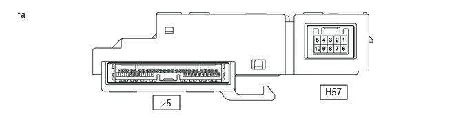
- STEERING SENSOR
*a Component without harness connected
(Steering Sensor)- - - Disconnect the cable from the negative (-) auxiliary battery terminal.
- Disconnect the H57 steering sensor connector.
- Measure the resistance according to the value(s) in the table below.
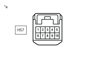
*a Front view of wire harness connector
(to Steering Sensor)Standard Resistance
Terminal No. (Symbol) Terminal Description Condition Specified Condition H57-3 (CANH) - H57-8 (CANL) HIGH-level CAN bus line - LOW-level CAN bus line Cable disconnected from negative (-) auxiliary battery terminal 54 to 69 Ω H57-3 (CANH) - H57-6 (ESS) HIGH-level CAN bus line - Ground Cable disconnected from negative (-) auxiliary battery terminal 200 Ω or higher H57-8 (CANL) - H57-6 (ESS) LOW-level CAN bus line - Ground Cable disconnected from negative (-) auxiliary battery terminal 200 Ω or higher H57-3 (CANH) - H57-4 (BAT) HIGH-level CAN bus line - Auxiliary battery positive (+) Cable disconnected from negative (-) auxiliary battery terminal 6 kΩ or higher H57-8 (CANL) - H57-4 (BAT) LOW-level CAN bus line - Auxiliary battery positive (+) Cable disconnected from negative (-) auxiliary battery terminal 6 kΩ or higher
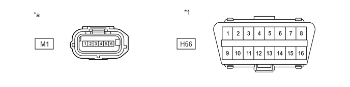
- YAW RATE SENSOR
*a Component without harness connected
(Yaw Rate Sensor)- - - Disconnect the cable from the negative (-) auxiliary battery terminal.
- Disconnect the M1 yaw rate sensor assembly connector.
- Measure the resistance according to the value(s) in the table below.
*1 DLC3 - - *a Front view of wire harness connector
(to Yaw Rate Sensor)- - Standard Resistance
Terminal No. (Symbol) Terminal Description Condition Specified Condition M1-3 (CANH) - M1-2 (CANL) HIGH-level CAN bus line - LOW-level CAN bus line Cable disconnected from negative (-) auxiliary battery terminal 54 to 69 Ω M1-3 (CANH) - M1-1 (GND) HIGH-level CAN bus line - Ground Cable disconnected from negative (-) auxiliary battery terminal 200 Ω or higher M1-2 (CANL) - M1-1 (GND) LOW-level CAN bus line - Ground Cable disconnected from negative (-) auxiliary battery terminal 200 Ω or higher M1-3 (CANH) - H56-16 (BAT) HIGH-level CAN bus line - Auxiliary battery positive (+) Cable disconnected from negative (-) auxiliary battery terminal 6 kΩ or higher M1-2 (CANL) - H56-16 (BAT) LOW-level CAN bus line - Auxiliary battery positive (+) Cable disconnected from negative (-) auxiliary battery terminal 6 kΩ or higher
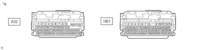
- HYBRID VEHICLE CONTROL ECU
Refer to Terminals of ECU.
- for 2WD
Refer to TERMINALS OF ECU [12/2019 - 11/2023]
- for AWD
Refer to TERMINALS OF ECU [12/2019 - 11/2023]
- Disconnect the cable from the negative (-) auxiliary battery terminal.
- Disconnect the A32 and H67 hybrid vehicle control ECU connectors.
- Measure the resistance according to the value(s) in the table below.
*a Front view of wire harness connector
(to Hybrid Vehicle Control ECU)- - Standard Resistance
BUS 2 BRANCH LINESTerminal No. (Symbol) Terminal Description Condition Specified Condition A32-21 (CA1H) - A32-8 (CA1L) HIGH-level CAN bus line - LOW-level CAN bus line Cable disconnected from negative (-) auxiliary battery terminal 54 to 69 Ω A32-21 (CA1H) - H67-3 (E1) HIGH-level CAN bus line - Ground Cable disconnected from negative (-) auxiliary battery terminal 200 Ω or higher A32-8 (CA1L) - H67-3 (E1) LOW-level CAN bus line - Ground Cable disconnected from negative (-) auxiliary battery terminal 200 Ω or higher A32-21 (CA1H) - H67-27 (BATT) HIGH-level CAN bus line - Auxiliary battery positive (+) Cable disconnected from negative (-) auxiliary battery terminal 6 kΩ or higher A32-8 (CA1L) - H67-27 (BATT) LOW-level CAN bus line - Auxiliary battery positive (+) Cable disconnected from negative (-) auxiliary battery terminal 6 kΩ or higher BUS 4 BRANCH LINESTerminal No. (Symbol) Terminal Description Condition Specified Condition A32-7 (CA3P) - A32-20 (CA3N) HIGH-level CAN bus line - LOW-level CAN bus line Cable disconnected from negative (-) auxiliary battery terminal 54 to 69 Ω A32-7 (CA3P) - H67-3 (E1) HIGH-level CAN bus line - Ground Cable disconnected from negative (-) auxiliary battery terminal 200 Ω or higher A32-20 (CA3N) - H67-3 (E1) LOW-level CAN bus line - Ground Cable disconnected from negative (-) auxiliary battery terminal 200 Ω or higher A32-7 (CA3P) - H67-27 (BATT) HIGH-level CAN bus line - Auxiliary battery positive (+) Cable disconnected from negative (-) auxiliary battery terminal 6 kΩ or higher A32-20 (CA3N) - H67-27 (BATT) LOW-level CAN bus line - Auxiliary battery positive (+) Cable disconnected from negative (-) auxiliary battery terminal 6 kΩ or higher
- for 2WD
- INVERTER WITH CONVERTER ASSEMBLY
Refer to Terminals of ECU.
- for 2WD
Refer to TERMINALS OF ECU [12/2019 - 11/2023]
- for AWD
Refer to TERMINALS OF ECU [12/2019 - 11/2023]
- Disconnect the cable from the negative (-) auxiliary battery terminal.
- Disconnect the A55 inverter with converter assembly connector.
- Measure the resistance according to the value(s) in the table below.
*1 DLC3 - - *a Front view of wire harness connector
(to Inverter with Converter Assembly)- - Standard Resistance
Terminal No. (Symbol) Terminal Description Condition Specified Condition A55-22 (CANH) - A55-31 (CANL) HIGH-level CAN bus line - LOW-level CAN bus line Cable disconnected from negative (-) auxiliary battery terminal 54 to 69 Ω A55-22 (CANH) - A55-9 (GND1) HIGH-level CAN bus line - Ground Cable disconnected from negative (-) auxiliary battery terminal 200 Ω or higher A55-31 (CANL) - A55-9 (GND1) LOW-level CAN bus line - Ground Cable disconnected from negative (-) auxiliary battery terminal 200 Ω or higher A55-22 (CANH) - H56-16 (BAT) HIGH-level CAN bus line - Auxiliary battery positive (+) Cable disconnected from negative (-) auxiliary battery terminal 6 kΩ or higher A55-31 (CANL) - H56-16 (BAT) LOW-level CAN bus line - Auxiliary battery positive (+) Cable disconnected from negative (-) auxiliary battery terminal 6 kΩ or higher FOR AWDTerminal No. (Symbol) Terminal Description Condition Specified Condition A55-24 (CNH2) - A55-33 (CNL2) HIGH-level CAN bus line - LOW-level CAN bus line Cable disconnected from negative (-) auxiliary battery terminal 54 to 69 Ω A55-24 (CNH2) - A55-9 (GND1) HIGH-level CAN bus line - Ground Cable disconnected from negative (-) auxiliary battery terminal 200 Ω or higher A55-33 (CNL2) - A55-9 (GND1) LOW-level CAN bus line - Ground Cable disconnected from negative (-) auxiliary battery terminal 200 Ω or higher A55-24 (CNH2) - H56-16 (BAT) HIGH-level CAN bus line - Auxiliary battery positive (+) Cable disconnected from negative (-) auxiliary battery terminal 6 kΩ or higher A55-33 (CNL2) - H56-16 (BAT) LOW-level CAN bus line - Auxiliary battery positive (+) Cable disconnected from negative (-) auxiliary battery terminal 6 kΩ or higher
- for 2WD
- ECM
Refer to Terminals of ECU.
Refer to TERMINALS OF ECM [12/2019 - 10/2021]
- Disconnect the cable from the negative (-) auxiliary battery terminal.
- Disconnect the A27 ECM connector.
- Measure the resistance according to the value(s) in the table below.
*a Front view of wire harness connector
(to ECM)- - Standard Resistance
BUS 2 MAIN LINESTerminal No. (Symbol) Terminal Description Condition Specified Condition A27-8 (CANH) - A27-18 (CANL) HIGH-level CAN bus line - LOW-level CAN bus line Cable disconnected from negative (-) auxiliary battery terminal 108 to 132 Ω A27-8 (CANH) - A27-10 (E1) HIGH-level CAN bus line - Ground Cable disconnected from negative (-) auxiliary battery terminal 200 Ω or higher A27-18 (CANL) - A27-10 (E1) LOW-level CAN bus line - Ground Cable disconnected from negative (-) auxiliary battery terminal 200 Ω or higher A27-8 (CANH) - A27-1 (BATT) HIGH-level CAN bus line - Auxiliary battery positive (+) Cable disconnected from negative (-) auxiliary battery terminal 6 kΩ or higher A27-18 (CANL) - A27-1 (BATT) LOW-level CAN bus line - Auxiliary battery positive (+) Cable disconnected from negative (-) auxiliary battery terminal 6 kΩ or higher BUS 4 BRANCH LINESTerminal No. (Symbol) Terminal Description Condition Specified Condition A27-7 (CAN+) - A27-17 (CAN-) HIGH-level CAN bus line - LOW-level CAN bus line Cable disconnected from negative (-) auxiliary battery terminal 54 to 69 Ω A27-7 (CAN+) - A27-10 (E1) HIGH-level CAN bus line - Ground Cable disconnected from negative (-) auxiliary battery terminal 200 Ω or higher A27-17 (CAN-) - A27-10 (E1) LOW-level CAN bus line - Ground Cable disconnected from negative (-) auxiliary battery terminal 200 Ω or higher A27-7 (CAN+) - A27-1 (BATT) HIGH-level CAN bus line - Auxiliary battery positive (+) Cable disconnected from negative (-) auxiliary battery terminal 6 kΩ or higher A27-17 (CAN-) - A27-1 (BATT) LOW-level CAN bus line - Auxiliary battery positive (+) Cable disconnected from negative (-) auxiliary battery terminal 6 kΩ or higher
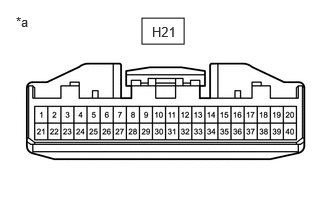
- COMBINATION METER ASSEMBLY
Refer to Terminals of ECU.
Refer to TERMINALS OF ECU [12/2019 - 11/2023]
- Disconnect the cable from the negative (-) auxiliary battery terminal.
- Disconnect the H21 combination meter assembly connector.
- Measure the resistance according to the value(s) in the table below.
*a Front view of wire harness connector
(to Combination Meter Assembly)Standard Resistance
Terminal No. (Symbol) Terminal Description Condition Specified Condition H21-32 (CANH) - H21-31 (CANL) HIGH-level CAN bus line - LOW-level CAN bus line Cable disconnected from negative (-) auxiliary battery terminal 108 to 132 Ω H21-32 (CANH) - H21-21 (ES) HIGH-level CAN bus line - Ground Cable disconnected from negative (-) auxiliary battery terminal 200 Ω or higher H21-31 (CANL) - H21-21 (ES) LOW-level CAN bus line - Ground Cable disconnected from negative (-) auxiliary battery terminal 200 Ω or higher H21-32 (CANH) - H21-40 (B) HIGH-level CAN bus line - Auxiliary battery positive (+) Cable disconnected from negative (-) auxiliary battery terminal 6 kΩ or higher H21-31 (CANL) - H21-40 (B) LOW-level CAN bus line - Auxiliary battery positive (+) Cable disconnected from negative (-) auxiliary battery terminal 6 kΩ or higher
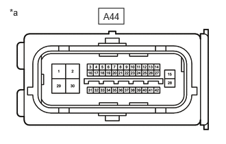
- NO. 1 SKID CONTROL ECU (BRAKE BOOSTER WITH MASTER CYLINDER ASSEMBLY)
Refer to Terminals of ECU.
Refer to TERMINALS OF ECU [12/2019 - ]
- Disconnect the cable from the negative (-) auxiliary battery terminal.
- Disconnect the A44 No. 1 skid control ECU (brake booster with master cylinder assembly) connector.
- Measure the resistance according to the value(s) in the table below.
Standard Resistance
BUS 2 BRANCH LINESTerminal No. (Symbol) Terminal Description Condition Specified Condition A44-35 (CA2H) - A44-36 (CA2L) HIGH-level CAN bus line - LOW-level CAN bus line Cable disconnected from negative (-) auxiliary battery terminal 54 to 69 Ω A44-35 (CA2H) - A44-28 (GND1) HIGH-level CAN bus line - Ground Cable disconnected from negative (-) auxiliary battery terminal 200 Ω or higher A44-36 (CA2L) - A44-28 (GND1) LOW-level CAN bus line - Ground Cable disconnected from negative (-) auxiliary battery terminal 200 Ω or higher A44-35 (CA2H) - A44-14 (+BI1) HIGH-level CAN bus line - Auxiliary battery positive (+) Cable disconnected from negative (-) auxiliary battery terminal 6 kΩ or higher A44-36 (CA2L) - A44-14 (+BI1) LOW-level CAN bus line - Auxiliary battery positive (+) Cable disconnected from negative (-) auxiliary battery terminal 6 kΩ or higher BUS 4 BRANCH LINESTerminal No. (Symbol) Terminal Description Condition Specified Condition A44-38 (CA1H) - A44-39 (CA1L) HIGH-level CAN bus line - LOW-level CAN bus line Cable disconnected from negative (-) auxiliary battery terminal 54 to 69 Ω A44-38 (CA1H) - A44-28 (GND1) HIGH-level CAN bus line - Ground Cable disconnected from negative (-) auxiliary battery terminal 200 Ω or higher A44-39 (CA1L) - A44-28 (GND1) LOW-level CAN bus line - Ground Cable disconnected from negative (-) auxiliary battery terminal 200 Ω or higher A44-38 (CA1H) - A44-14 (+BI1) HIGH-level CAN bus line - Auxiliary battery positive (+) Cable disconnected from negative (-) auxiliary battery terminal 6 kΩ or higher A44-39 (CA1L) - A44-14 (+BI1) LOW-level CAN bus line - Auxiliary battery positive (+) Cable disconnected from negative (-) auxiliary battery terminal 6 kΩ or higher *a Front view of wire harness connector
(to No. 1 Skid Control ECU (Brake Booster with Master Cylinder Assembly))
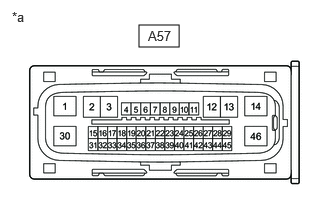
- NO. 2 SKID CONTROL ECU (BRAKE ACTUATOR ASSEMBLY)
Refer to Terminals of ECU.
Refer to TERMINALS OF ECU [12/2019 - ]
- Disconnect the cable from the negative (-) auxiliary battery terminal.
- Disconnect the A57 No. 2 skid control ECU (brake actuator assembly) connector.
- Measure the resistance according to the value(s) in the table below.
*a Front view of wire harness connector
(to No. 2 Skid Control ECU (Brake Actuator Assembly))Standard Resistance
BUS 2 BRANCH LINESTerminal No. (Symbol) Terminal Description Condition Specified Condition A57-16 (CA2H) - A57-17 (CA2L) HIGH-level CAN bus line - LOW-level CAN bus line Cable disconnected from negative (-) auxiliary battery terminal 54 to 69 Ω A57-16 (CA2H) - A57-1 (GND1) HIGH-level CAN bus line - Ground Cable disconnected from negative (-) auxiliary battery terminal 200 Ω or higher A57-17 (CA2L) - A57-1 (GND1) LOW-level CAN bus line - Ground Cable disconnected from negative (-) auxiliary battery terminal 200 Ω or higher A57-16 (CA2H) - A57-14 (+BS) HIGH-level CAN bus line - Auxiliary battery positive (+) Cable disconnected from negative (-) auxiliary battery terminal 6 kΩ or higher A57-17 (CA2L) - A57-14 (+BS) LOW-level CAN bus line - Auxiliary battery positive (+) Cable disconnected from negative (-) auxiliary battery terminal 6 kΩ or higher BUS 4 BRANCH LINESTerminal No. (Symbol) Terminal Description Condition Specified Condition A57-27 (CANH) - A57-43 (CANL) HIGH-level CAN bus line - LOW-level CAN bus line Cable disconnected from negative (-) auxiliary battery terminal 54 to 69 Ω A57-27 (CANH) - A57-1 (GND1) HIGH-level CAN bus line - Ground Cable disconnected from negative (-) auxiliary battery terminal 200 Ω or higher A57-43 (CANL) - A57-1 (GND1) LOW-level CAN bus line - Ground Cable disconnected from negative (-) auxiliary battery terminal 200 Ω or higher A57-27 (CANH) - A57-14 (+BS) HIGH-level CAN bus line - Auxiliary battery positive (+) Cable disconnected from negative (-) auxiliary battery terminal 6 kΩ or higher A57-43 (CANL) - A57-14 (+BS) LOW-level CAN bus line - Auxiliary battery positive (+) Cable disconnected from negative (-) auxiliary battery terminal 6 kΩ or higher
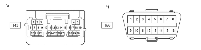
- MAIN BODY ECU (MULTIPLEX NETWORK BODY ECU)
Refer to Terminals of ECU.
Refer to TERMINALS OF ECU [12/2019 - 11/2023]
- Disconnect the cable from the negative (-) auxiliary battery terminal.
- Disconnect the H43 main body ECU (multiplex network body ECU) connector.
- Measure the resistance according to the value(s) in the table below.
*1 DLC3 - - *a Front view of wire harness connector
(to Main Body ECU (Multiplex Network Body ECU))- - Standard Resistance
Terminal No. (Symbol) Terminal Description Condition Specified Condition H43-5 (CANH) - H43-4 (CANL) HIGH-level CAN bus line - LOW-level CAN bus line Cable disconnected from negative (-) auxiliary battery terminal 54 to 69 Ω H43-5 (CANH) - H56-4 (CG) HIGH-level CAN bus line - Ground Cable disconnected from negative (-) auxiliary battery terminal 200 Ω or higher H43-4 (CANL) - H56-4 (CG) LOW-level CAN bus line - Ground Cable disconnected from negative (-) auxiliary battery terminal 200 Ω or higher H43-5 (CANH) - H56-16 (BAT) HIGH-level CAN bus line - Auxiliary battery positive (+) Cable disconnected from negative (-) auxiliary battery terminal 6 kΩ or higher H43-4 (CANL) - H56-16 (BAT) LOW-level CAN bus line - Auxiliary battery positive (+) Cable disconnected from negative (-) auxiliary battery terminal 6 kΩ or higher
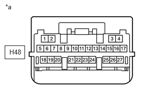
- CERTIFICATION ECU (SMART KEY ECU ASSEMBLY)
Refer to Terminals of ECU.
Refer to TERMINALS OF ECU [12/2019 - 10/2021]
- Disconnect the cable from the negative (-) auxiliary battery terminal.
- Disconnect the H48 certification ECU (smart key ECU assembly) connector.
- Measure the resistance according to the value(s) in the table below.
Standard Resistance
Terminal No. (Symbol) Terminal Description Condition Specified Condition H48-1 (CANH) - H48-2 (CANL) HIGH-level CAN bus line - LOW-level CAN bus line Cable disconnected from negative (-) auxiliary battery terminal 54 to 69 Ω H48-1 (CANH) - H48-18 (E) HIGH-level CAN bus line - Ground Cable disconnected from negative (-) auxiliary battery terminal 200 Ω or higher H48-2 (CANL) - H48-18 (E) LOW-level CAN bus line - Ground Cable disconnected from negative (-) auxiliary battery terminal 200 Ω or higher H48-1 (CANH) - H48-4 (+B) HIGH-level CAN bus line - Auxiliary battery positive (+) Cable disconnected from negative (-) auxiliary battery terminal 6 kΩ or higher H48-2 (CANL) - H48-4 (+B) LOW-level CAN bus line - Auxiliary battery positive (+) Cable disconnected from negative (-) auxiliary battery terminal 6 kΩ or higher *a Front view of wire harness connector
(to Certification ECU (Smart Key ECU Assembly))
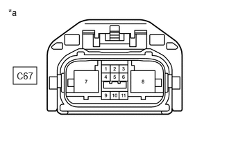
- RACK AND PINION POWER STEERING GEAR ASSEMBLY
Refer to Terminals of ECU.
Refer to TERMINALS OF ECU [12/2019 - ]
- Disconnect the cable from the negative (-) auxiliary battery terminal.
- Disconnect the C67 rack and pinion power steering gear assembly connector.
- Measure the resistance according to the value(s) in the table below.
*a Front view of wire harness connector
(to Rack and Pinion Power Steering Gear Assembly)Standard Resistance
Terminal No. (Symbol) Terminal Description Condition Specified Condition C67-10 (CANH) - C67-11 (CANL) HIGH-level CAN bus line - LOW-level CAN bus line Cable disconnected from negative (-) auxiliary battery terminal 54 to 69 Ω C67-10 (CANH) - C67-7 (PGND) HIGH-level CAN bus line - Ground Cable disconnected from negative (-) auxiliary battery terminal 200 Ω or higher C67-11 (CANL) - C67-7 (PGND) LOW-level CAN bus line - Ground Cable disconnected from negative (-) auxiliary battery terminal 200 Ω or higher C67-10 (CANH) - C67-8 (PIG) HIGH-level CAN bus line - Auxiliary battery positive (+) Cable disconnected from negative (-) auxiliary battery terminal 6 kΩ or higher C67-11 (CANL) - C67-8 (PIG) LOW-level CAN bus line - Auxiliary battery positive (+) Cable disconnected from negative (-) auxiliary battery terminal 6 kΩ or higher
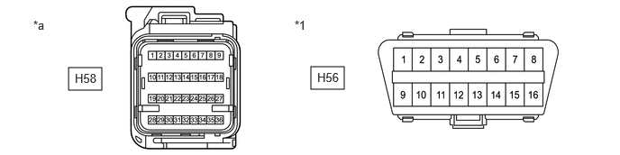
- AIRBAG SENSOR ASSEMBLY
Refer to Terminals of ECU.
Refer to TERMINALS OF ECU [12/2019 - 10/2021]
- Disconnect the cable from the negative (-) auxiliary battery terminal.
- Disconnect the H58 airbag sensor assembly connector.
- Measure the resistance according to the value(s) in the table below.
*1 DLC3 - - *a Front view of wire harness connector
(to Airbag Sensor Assembly)- - Standard Resistance
Terminal No. (Symbol) Terminal Description Condition Specified Condition H58-26 (CANH) - H58-27 (CANL) HIGH-level CAN bus line - LOW-level CAN bus line Cable disconnected from negative (-) auxiliary battery terminal 108 to 132 Ω H58-26 (CANH) - H58-33 (E1) HIGH-level CAN bus line - Ground Cable disconnected from negative (-) auxiliary battery terminal 200 Ω or higher H58-27 (CANL) - H58-33 (E1) LOW-level CAN bus line - Ground Cable disconnected from negative (-) auxiliary battery terminal 200 Ω or higher H58-26 (CANH) - H56-16 (BAT) HIGH-level CAN bus line - Auxiliary battery positive (+) Cable disconnected from negative (-) auxiliary battery terminal 6 kΩ or higher H58-27 (CANL) - H56-16 (BAT) LOW-level CAN bus line - Auxiliary battery positive (+) Cable disconnected from negative (-) auxiliary battery terminal 6 kΩ or higher
- AIR CONDITIONING AMPLIFIER ASSEMBLY
Refer to Terminals of ECU.
Refer to TERMINALS OF ECU [12/2019 - 10/2021]
- Disconnect the cable from the negative (-) auxiliary battery terminal.
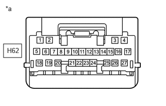
- Disconnect the H62 air conditioning amplifier assembly connector.
- Measure the resistance according to the value(s) in the table below.
Standard Resistance
Terminal No. (Symbol) Terminal Description Condition Specified Condition H62-2 (CANH) - H62-1 (CANL) HIGH-level CAN bus line - LOW-level CAN bus line Cable disconnected from negative (-) auxiliary battery terminal 54 to 69 Ω H62-2 (CANH) - H62-17 (GND) HIGH-level CAN bus line - Ground Cable disconnected from negative (-) auxiliary battery terminal 200 Ω or higher H62-1 (CANL) - H62-17 (GND) LOW-level CAN bus line - Ground Cable disconnected from negative (-) auxiliary battery terminal 200 Ω or higher H62-2 (CANH) - H62-5 (B) HIGH-level CAN bus line - Auxiliary battery positive (+) Cable disconnected from negative (-) auxiliary battery terminal 6 kΩ or higher H62-1 (CANL) - H62-5 (B) LOW-level CAN bus line - Auxiliary battery positive (+) Cable disconnected from negative (-) auxiliary battery terminal 6 kΩ or higher *a Front view of wire harness connector
(to Air Conditioning Amplifier Assembly)
- RADIO AND DISPLAY RECEIVER ASSEMBLY (for 8 Inch Display)
Refer to Terminals of ECU.
- for Navigation System
Refer to TERMINALS OF ECU [12/2019 - 10/2022]
- for Audio and Visual System
Refer to TERMINALS OF ECU [12/2019 - 10/2022]
- Disconnect the cable from the negative (-) auxiliary battery terminal.
- Disconnect the H2 radio and display receiver assembly connector.
- Measure the resistance according to the value(s) in the table below.
*1 DLC3 - - *a Front view of wire harness connector
(to Radio and Display Receiver Assembly)- - Standard Resistance
Terminal No. (Symbol) Terminal Description Condition Specified Condition H2-13 (CANH) - H2-14 (CANL) HIGH-level CAN bus line - LOW-level CAN bus line Cable disconnected from negative (-) auxiliary battery terminal 54 to 69 Ω H2-13 (CANH) - H56-4 (CG) HIGH-level CAN bus line - Ground Cable disconnected from negative (-) auxiliary battery terminal 200 Ω or higher H2-14 (CANL) - H56-4 (CG) LOW-level CAN bus line - Ground Cable disconnected from negative (-) auxiliary battery terminal 200 Ω or higher H2-13 (CANH) - H56-16 (BAT) HIGH-level CAN bus line - Auxiliary battery positive (+) Cable disconnected from negative (-) auxiliary battery terminal 6 kΩ or higher H2-14 (CANL) - H56-16 (BAT) LOW-level CAN bus line - Auxiliary battery positive (+) Cable disconnected from negative (-) auxiliary battery terminal 6 kΩ or higher
- for Navigation System
- RADIO RECEIVER ASSEMBLY (for 12.3 Inch Display)
Refer to Terminals of ECU.
Refer to TERMINALS OF ECU [12/2019 - 10/2022]
- Disconnect the cable from the negative (-) auxiliary battery terminal.
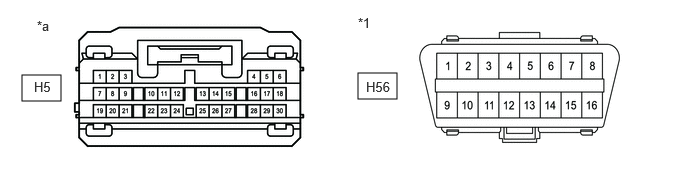
- Disconnect the H5 radio receiver assembly connector.
- Measure the resistance according to the value(s) in the table below.
*1 DLC3 - - *a Front view of wire harness connector
(to Radio Receiver Assembly)- - Standard Resistance
Terminal No. (Symbol) Terminal Description Condition Specified Condition H5-13 (CANH) - H5-14 (CANL) HIGH-level CAN bus line - LOW-level CAN bus line Cable disconnected from negative (-) auxiliary battery terminal 54 to 69 Ω H5-13 (CANH) - H56-4 (CG) HIGH-level CAN bus line - Ground Cable disconnected from negative (-) auxiliary battery terminal 200 Ω or higher H5-14 (CANL) - H56-4 (CG) LOW-level CAN bus line - Ground Cable disconnected from negative (-) auxiliary battery terminal 200 Ω or higher H5-13 (CANH) - H56-16 (BAT) HIGH-level CAN bus line - Auxiliary battery positive (+) Cable disconnected from negative (-) auxiliary battery terminal 6 kΩ or higher H5-14 (CANL) - H56-16 (BAT) LOW-level CAN bus line - Auxiliary battery positive (+) Cable disconnected from negative (-) auxiliary battery terminal 6 kΩ or higher
- BLIND SPOT MONITOR SENSOR LH
Refer to Terminals of ECU.
Refer to TERMINALS OF ECU [12/2019 - 11/2023]
- Disconnect the cable from the negative (-) auxiliary battery terminal.
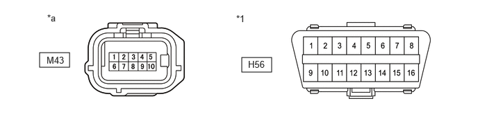
- Disconnect the M43 blind spot monitor sensor LH connector.
- Measure the resistance according to the value(s) in the table below.
*1 DLC3 - - *a Front view of wire harness connector
(to Blind Spot Monitor Sensor LH)- - Standard Resistance
Terminal No. (Symbol) Terminal Description Condition Specified Condition M43-2 (CA1P) - M43-7 (CA1N) HIGH-level CAN bus line - LOW-level CAN bus line Cable disconnected from negative (-) auxiliary battery terminal 54 to 69 Ω M43-2 (CA1P) - M43-10 (BLGD) HIGH-level CAN bus line - Ground Cable disconnected from negative (-) auxiliary battery terminal 200 Ω or higher M43-7 (CA1N) - M43-10 (BLGD) LOW-level CAN bus line - Ground Cable disconnected from negative (-) auxiliary battery terminal 200 Ω or higher M43-2 (CA1P) - H56-16 (BAT) HIGH-level CAN bus line - Auxiliary battery positive (+) Cable disconnected from negative (-) auxiliary battery terminal 6 kΩ or higher M43-7 (CA1N) - H56-16 (BAT) LOW-level CAN bus line - Auxiliary battery positive (+) Cable disconnected from negative (-) auxiliary battery terminal 6 kΩ or higher
- FORWARD RECOGNITION CAMERA
Refer to Terminals of ECU.
Refer to TERMINALS OF ECU [12/2019 - ]
- Disconnect the cable from the negative (-) auxiliary battery terminal.
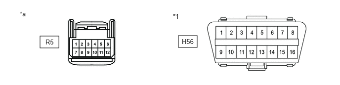
- Disconnect the R5 forward recognition camera connector.
- Measure the resistance according to the value(s) in the table below.
*1 DLC3 - - *a Front view of wire harness connector
(to Forward Recognition Camera)- - Standard Resistance
Terminal No. (Symbol) Terminal Description Condition Specified Condition R5-5 (CA1P) - R5-11 (CA1N) HIGH-level CAN bus line - LOW-level CAN bus line Cable disconnected from negative (-) auxiliary battery terminal 54 to 69 Ω R5-5 (CA1P) - R5-10 (GND) HIGH-level CAN bus line - Ground Cable disconnected from negative (-) auxiliary battery terminal 200 Ω or higher R5-11 (CA1N) - R5-10 (GND) LOW-level CAN bus line - Ground Cable disconnected from negative (-) auxiliary battery terminal 200 Ω or higher R5-5 (CA1P) - H56-16 (BAT) HIGH-level CAN bus line - Auxiliary battery positive (+) Cable disconnected from negative (-) auxiliary battery terminal 6 kΩ or higher R5-11 (CA1N) - H56-16 (BAT) LOW-level CAN bus line - Auxiliary battery positive (+) Cable disconnected from negative (-) auxiliary battery terminal 6 kΩ or higher
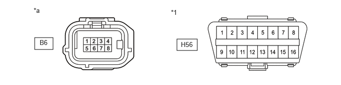
- MILLIMETER WAVE RADAR SENSOR ASSEMBLY
Refer to Terminals of ECU.
Refer to TERMINALS OF ECU [12/2019 - ]
- Disconnect the cable from the negative (-) auxiliary battery terminal.
- Disconnect the B6 millimeter wave radar sensor assembly connector.
- Measure the resistance according to the value(s) in the table below.
*1 DLC3 - - *a Front view of wire harness connector
(to Millimeter Wave Radar Sensor Assembly)- - Standard Resistance
Terminal No. (Symbol) Terminal Description Condition Specified Condition B6-3 (CA2H) - B6-2 (CA2L) HIGH-level CAN bus line - LOW-level CAN bus line Cable disconnected from negative (-) auxiliary battery terminal 54 to 69 Ω B6-3 (CA2H) - B6-1 (SGND) HIGH-level CAN bus line - Ground Cable disconnected from negative (-) auxiliary battery terminal 200 Ω or higher B6-2 (CA2L) - B6-1 (SGND) LOW-level CAN bus line - Ground Cable disconnected from negative (-) auxiliary battery terminal 200 Ω or higher B6-3 (CA2H) - H56-16 (BAT) HIGH-level CAN bus line - Auxiliary battery positive (+) Cable disconnected from negative (-) auxiliary battery terminal 6 kΩ or higher B6-2 (CA2L) - H56-16 (BAT) LOW-level CAN bus line - Auxiliary battery positive (+) Cable disconnected from negative (-) auxiliary battery terminal 6 kΩ or higher
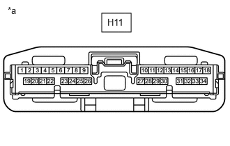
- DCM (TELEMATICS TRANSCEIVER) (w/ Telematics Transceiver)
Refer to Terminals of ECU.
Refer to TERMINALS OF ECU [12/2019 - 10/2021]
- Disconnect the cable from the negative (-) auxiliary battery terminal.
- Disconnect the H11 DCM (telematics transceiver) connector.
- Measure the resistance according to the value(s) in the table below.
Standard Resistance
Terminal No. (Symbol) Terminal Description Condition Specified Condition H11-25 (CANP) - H11-26 (CANN) HIGH-level CAN bus line - LOW-level CAN bus line Cable disconnected from negative (-) auxiliary battery terminal 54 to 69 Ω H11-25 (CANP) - H11-20 (E) HIGH-level CAN bus line - Ground Cable disconnected from negative (-) auxiliary battery terminal 200 Ω or higher H11-26 (CANN) - H11-20 (E) LOW-level CAN bus line - Ground Cable disconnected from negative (-) auxiliary battery terminal 200 Ω or higher H11-25 (CANP) - H11-1 (+B) HIGH-level CAN bus line - Auxiliary battery positive (+) Cable disconnected from negative (-) auxiliary battery terminal 6 kΩ or higher H11-26 (CANN) - H11-1 (+B) LOW-level CAN bus line - Auxiliary battery positive (+) Cable disconnected from negative (-) auxiliary battery terminal 6 kΩ or higher *a Front view of wire harness connector
(to DCM (Telematics Transceiver))
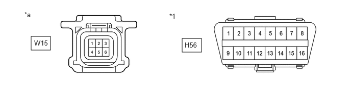
- REAR TELEVISION CAMERA ASSEMBLY (w/ Parking Assist Monitor System or Panoramic View Monitor System)
Refer to Terminals of ECU.
- w/ Parking Assist Monitor System
Refer to TERMINALS OF ECU [12/2019 - 10/2022]
- w/ Panoramic View Monitor System
Refer to TERMINALS OF ECU [12/2019 - 10/2022]
- Disconnect the cable from the negative (-) auxiliary battery terminal.
- Disconnect the W15 rear television camera assembly connector.
- Measure the resistance according to the value(s) in the table below.
*1 DLC3 - - *a Front view of wire harness connector
(to Rear Television Camera Assembly)- - Standard Resistance
Terminal No. (Symbol) Terminal Description Condition Specified Condition W15-4 (CANH) - W15-1 (CANL) HIGH-level CAN bus line - LOW-level CAN bus line Cable disconnected from negative (-) auxiliary battery terminal 54 to 69 Ω W15-4 (CANH) - H56-4 (CG) HIGH-level CAN bus line - Ground Cable disconnected from negative (-) auxiliary battery terminal 200 Ω or higher W15-1 (CANL) - H56-4 (CG) LOW-level CAN bus line - Ground Cable disconnected from negative (-) auxiliary battery terminal 200 Ω or higher W15-4 (CANH) - H56-16 (BAT) HIGH-level CAN bus line - Auxiliary battery positive (+) Cable disconnected from negative (-) auxiliary battery terminal 6 kΩ or higher W15-1 (CANL) - H56-16 (BAT) LOW-level CAN bus line - Auxiliary battery positive (+) Cable disconnected from negative (-) auxiliary battery terminal 6 kΩ or higher
- w/ Parking Assist Monitor System
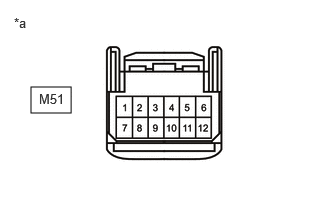
- TIRE PRESSURE WARNING ECU AND RECEIVER
Refer to Terminals of ECU.
Refer to TERMINALS OF ECU [12/2019 - 11/2023]
- Disconnect the cable from the negative (-) auxiliary battery terminal.
- Disconnect the M51 tire pressure warning ECU and receiver connector.
- Measure the resistance according to the value(s) in the table below.
*a Front view of wire harness connector
(to Tire Pressure Warning ECU and Receiver)Standard Resistance
Terminal No. (Symbol) Terminal Description Condition Specified Condition M51-9 (CANH) - M51-10 (CANL) HIGH-level CAN bus line - LOW-level CAN bus line Cable disconnected from negative (-) auxiliary battery terminal 54 to 69 Ω M51-9 (CANH) - M51-12 (GND) HIGH-level CAN bus line - Ground Cable disconnected from negative (-) auxiliary battery terminal 200 Ω or higher M51-10 (CANL) - M51-12 (GND) LOW-level CAN bus line - Ground Cable disconnected from negative (-) auxiliary battery terminal 200 Ω or higher M51-9 (CANH) - M51-7 (+B) HIGH-level CAN bus line - Auxiliary battery positive (+) Cable disconnected from negative (-) auxiliary battery terminal 6 kΩ or higher M51-10 (CANL) - M51-7 (+B) LOW-level CAN bus line - Auxiliary battery positive (+) Cable disconnected from negative (-) auxiliary battery terminal 6 kΩ or higher
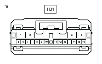
- METER MIRROR SUB-ASSEMBLY (w/ Headup Display System)
Refer to Terminals of ECU.
Refer to TERMINALS OF ECU [12/2019 - ]
- Disconnect the cable from the negative (-) auxiliary battery terminal.
- Disconnect the H31 meter mirror sub-assembly connector.
- Measure the resistance according to the value(s) in the table below.
*a Front view of wire harness connector
(to Meter Mirror Sub-assembly)Standard Resistance
Terminal No. (Symbol) Terminal Description Condition Specified Condition H31-12 (MPX1) - H31-13 (MPX2) HIGH-level CAN bus line - LOW-level CAN bus line Cable disconnected from negative (-) auxiliary battery terminal 54 to 69 Ω H31-12 (MPX1) - H31-4 (ES) HIGH-level CAN bus line - Ground Cable disconnected from negative (-) auxiliary battery terminal 200 Ω or higher H31-13 (MPX2) - H31-4 (ES) LOW-level CAN bus line - Ground Cable disconnected from negative (-) auxiliary battery terminal 200 Ω or higher H31-12 (MPX1) - H31-2 (B) HIGH-level CAN bus line - Auxiliary battery positive (+) Cable disconnected from negative (-) auxiliary battery terminal 6 kΩ or higher H31-13 (MPX2) - H31-2 (B) LOW-level CAN bus line - Auxiliary battery positive (+) Cable disconnected from negative (-) auxiliary battery terminal 6 kΩ or higher
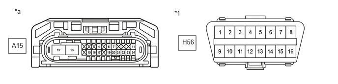
- HEADLIGHT ECU SUB-ASSEMBLY LH (w/ AFS)
Refer to Terminals of ECU.
Refer to TERMINALS OF ECU [12/2019 - 10/2022]
- Disconnect the cable from the negative (-) auxiliary battery terminal.
- Disconnect the A15 headlight ECU sub-assembly LH connector.
- Measure the resistance according to the value(s) in the table below.
*1 DLC3 - - *a Front view of wire harness connector
(to Headlight ECU Sub-assembly LH)- - Standard Resistance
Terminal No. (Symbol) Terminal Description Condition Specified Condition A15-24 (CANH) - A15-23 (CANL) HIGH-level CAN bus line - LOW-level CAN bus line Cable disconnected from negative (-) auxiliary battery terminal 54 to 69 Ω A15-24 (CANH) - A15-12 (GND) HIGH-level CAN bus line - Ground Cable disconnected from negative (-) auxiliary battery terminal 200 Ω or higher A15-23 (CANL) - A15-12 (GND) LOW-level CAN bus line - Ground Cable disconnected from negative (-) auxiliary battery terminal 200 Ω or higher A15-24 (CANH) - H56-16 (BAT) HIGH-level CAN bus line - Auxiliary battery positive (+) Cable disconnected from negative (-) auxiliary battery terminal 6 kΩ or higher A15-23 (CANL) - H56-16 (BAT) LOW-level CAN bus line - Auxiliary battery positive (+) Cable disconnected from negative (-) auxiliary battery terminal 6 kΩ or higher
- HEADLIGHT ECU SUB-ASSEMBLY RH (w/ AFS)
Refer to Terminals of ECU.
Refer to TERMINALS OF ECU [12/2019 - 10/2022]
- Disconnect the cable from the negative (-) auxiliary battery terminal.
- Disconnect the A16 headlight ECU sub-assembly RH connector.
- Measure the resistance according to the value(s) in the table below.
*1 DLC3 - - *a Front view of wire harness connector
(to Headlight ECU Sub-assembly RH)- - Standard Resistance
Terminal No. (Symbol) Terminal Description Condition Specified Condition A16-24 (CANH) - A16-23 (CANL) HIGH-level CAN bus line - LOW-level CAN bus line Cable disconnected from negative (-) auxiliary battery terminal 54 to 69 Ω A16-24 (CANH) - A16-12 (GND) HIGH-level CAN bus line - Ground Cable disconnected from negative (-) auxiliary battery terminal 200 Ω or higher A16-23 (CANL) - A16-12 (GND) LOW-level CAN bus line - Ground Cable disconnected from negative (-) auxiliary battery terminal 200 Ω or higher A16-24 (CANH) - H56-16 (BAT) HIGH-level CAN bus line - Auxiliary battery positive (+) Cable disconnected from negative (-) auxiliary battery terminal 6 kΩ or higher A16-23 (CANL) - H56-16 (BAT) LOW-level CAN bus line - Auxiliary battery positive (+) Cable disconnected from negative (-) auxiliary battery terminal 6 kΩ or higher
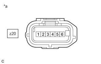
- SWING GRILLE ACTUATOR ASSEMBLY
Refer to Terminals of ECU.
Refer to TERMINALS OF ECU [12/2019 - 10/2021]
- Disconnect the cable from the negative (-) auxiliary battery terminal.
- Disconnect the z20 swing grille actuator assembly connector.
- Measure the resistance according to the value(s) in the table below.
*a Front view of wire harness connector
(to Swing Grille Actuator Assembly)Standard Resistance
Terminal No. (Symbol) Terminal Description Condition Specified Condition z20-6 (CAN-P) - z20-5 (CAN-N) HIGH-level CAN bus line - LOW-level CAN bus line Cable disconnected from negative (-) auxiliary battery terminal 54 to 69 Ω z20-6 (CAN-P) - z20-3 (GND) HIGH-level CAN bus line - Ground Cable disconnected from negative (-) auxiliary battery terminal 200 Ω or higher z20-5 (CAN-N) - z20-3 (GND) LOW-level CAN bus line - Ground Cable disconnected from negative (-) auxiliary battery terminal 200 Ω or higher z20-6 (CAN-P) - z20-1 (+B) HIGH-level CAN bus line - Auxiliary battery positive (+) Cable disconnected from negative (-) auxiliary battery terminal 6 kΩ or higher z20-5 (CAN-N) - z20-1 (+B) LOW-level CAN bus line - Auxiliary battery positive (+) Cable disconnected from negative (-) auxiliary battery terminal 6 kΩ or higher
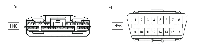
- CLEARANCE WARNING ECU ASSEMBLY (w/ Intuitive Parking Assist System)
Refer to Terminals of ECU.
Refer to TERMINALS OF ECU [12/2019 - 11/2023]
- Disconnect the cable from the negative (-) auxiliary battery terminal.
- Disconnect the H46 clearance warning ECU assembly connector.
- Measure the resistance according to the value(s) in the table below.
*1 DLC3 - - *a Front view of wire harness connector
(to Clearance Warning ECU Assembly)- - Standard Resistance
Terminal No. (Symbol) Terminal Description Condition Specified Condition H46-17 (R1) - H46-18 (R2) HIGH-level CAN bus line - LOW-level CAN bus line Cable disconnected from negative (-) auxiliary battery terminal 54 to 69 Ω H46-17 (R1) - H46-28 (E) HIGH-level CAN bus line - Ground Cable disconnected from negative (-) auxiliary battery terminal 200 Ω or higher H46-18 (R2) - H46-28 (E) LOW-level CAN bus line - Ground Cable disconnected from negative (-) auxiliary battery terminal 200 Ω or higher H46-17 (R1) - H56-16 (BAT) HIGH-level CAN bus line - Auxiliary battery positive (+) Cable disconnected from negative (-) auxiliary battery terminal 6 kΩ or higher H46-18 (R2) - H56-16 (BAT) LOW-level CAN bus line - Auxiliary battery positive (+) Cable disconnected from negative (-) auxiliary battery terminal 6 kΩ or higher
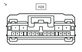
- PARKING ASSIST ECU (w/ Panoramic View Monitor System)
Refer to Terminals of ECU.
Refer to TERMINALS OF ECU [12/2019 - 10/2022]
- Disconnect the cable from the negative (-) auxiliary battery terminal.
- Disconnect the H20 parking assist ECU connector.
- Measure the resistance according to the value(s) in the table below.
*a Front view of wire harness connector
(to Parking Assist ECU)Standard Resistance
Terminal No. (Symbol) Terminal Description Condition Specified Condition H20-11 (CANH) - H20-12 (CANL) HIGH-level CAN bus line - LOW-level CAN bus line Cable disconnected from negative (-) auxiliary battery terminal 54 to 69 Ω H20-11 (CANH) - H20-4 (GND1) HIGH-level CAN bus line - Ground Cable disconnected from negative (-) auxiliary battery terminal 200 Ω or higher H20-12 (CANL) - H20-4 (GND1) LOW-level CAN bus line - Ground Cable disconnected from negative (-) auxiliary battery terminal 200 Ω or higher H20-11 (CANH) - H20-1 (+B) HIGH-level CAN bus line - Auxiliary battery positive (+) Cable disconnected from negative (-) auxiliary battery terminal 6 kΩ or higher H20-12 (CANL) - H20-1 (+B) LOW-level CAN bus line - Auxiliary battery positive (+) Cable disconnected from negative (-) auxiliary battery terminal 6 kΩ or higher
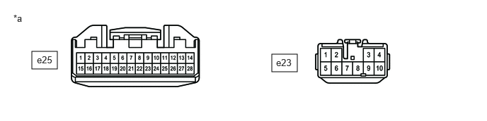
- POSITION CONTROL ECU ASSEMBLY LH (w/ Seat Position Memory System)
Refer to Terminals of ECU.
Refer to TERMINALS OF ECU [12/2019 - 11/2023]
- Disconnect the cable from the negative (-) auxiliary battery terminal.
- Disconnect the e23 and e25 position control ECU assembly LH connectors.
- Measure the resistance according to the value(s) in the table below.
*a Front view of wire harness connector
(to Position Control ECU Assembly LH)- - Standard Resistance
Terminal No. (Symbol) Terminal Description Condition Specified Condition e25-13 (CANP) - e25-14 (CANN) HIGH-level CAN bus line - LOW-level CAN bus line Cable disconnected from negative (-) auxiliary battery terminal 54 to 69 Ω e25-13 (CANP) - e23-2 (GND) HIGH-level CAN bus line - Ground Cable disconnected from negative (-) auxiliary battery terminal 200 Ω or higher e25-14 (CANN) - e23-2 (GND) LOW-level CAN bus line - Ground Cable disconnected from negative (-) auxiliary battery terminal 200 Ω or higher e25-13 (CANP) - e23-3 (+B) HIGH-level CAN bus line - Auxiliary battery positive (+) Cable disconnected from negative (-) auxiliary battery terminal 6 kΩ or higher e25-14 (CANN) - e23-3 (+B) LOW-level CAN bus line - Auxiliary battery positive (+) Cable disconnected from negative (-) auxiliary battery terminal 6 kΩ or higher
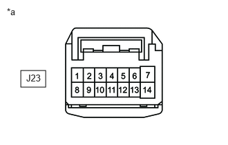
- OUTER MIRROR CONTROL ECU ASSEMBLY LH (w/ Seat Position Memory System)
Refer to Terminals of ECU.
Refer to TERMINALS OF ECU [12/2019 - 10/2022]
- Disconnect the cable from the negative (-) auxiliary battery terminal.
- Disconnect the J23 outer mirror control ECU assembly LH connector.
- Measure the resistance according to the value(s) in the table below.
*a Front view of wire harness connector
(to Outer Mirror Control ECU Assembly LH)Standard Resistance
Terminal No. (Symbol) Terminal Description Condition Specified Condition J23-9 (CANP) - J23-8 (CANN) HIGH-level CAN bus line - LOW-level CAN bus line Cable disconnected from negative (-) auxiliary battery terminal 54 to 69 Ω J23-9 (CANP) - J23-7 (GND) HIGH-level CAN bus line - Ground Cable disconnected from negative (-) auxiliary battery terminal 200 Ω or higher J23-8 (CANN) - J23-7 (GND) LOW-level CAN bus line - Ground Cable disconnected from negative (-) auxiliary battery terminal 200 Ω or higher J23-9 (CANP) - J23-6 (CPUB) HIGH-level CAN bus line - Auxiliary battery positive (+) Cable disconnected from negative (-) auxiliary battery terminal 6 kΩ or higher J23-8 (CANN) - J23-6 (CPUB) LOW-level CAN bus line - Auxiliary battery positive (+) Cable disconnected from negative (-) auxiliary battery terminal 6 kΩ or higher
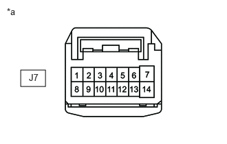
- OUTER MIRROR CONTROL ECU ASSEMBLY RH (w/ Seat Position Memory System)
Refer to Terminals of ECU.
Refer to TERMINALS OF ECU [12/2019 - 10/2022]
- Disconnect the cable from the negative (-) auxiliary battery terminal.
- Disconnect the J7 outer mirror control ECU assembly RH connector.
- Measure the resistance according to the value(s) in the table below.
*a Front view of wire harness connector
(to Outer Mirror Control ECU Assembly RH)Standard Resistance
Terminal No. (Symbol) Terminal Description Condition Specified Condition J7-9 (CANP) - J7-8 (CANN) HIGH-level CAN bus line - LOW-level CAN bus line Cable disconnected from negative (-) auxiliary battery terminal 54 to 69 Ω J7-9 (CANP) - J7-7 (GND) HIGH-level CAN bus line - Ground Cable disconnected from negative (-) auxiliary battery terminal 200 Ω or higher J7-8 (CANN) - J7-7 (GND) LOW-level CAN bus line - Ground Cable disconnected from negative (-) auxiliary battery terminal 200 Ω or higher J7-9 (CANP) - J7-6 (CPUB) HIGH-level CAN bus line - Auxiliary battery positive (+) Cable disconnected from negative (-) auxiliary battery terminal 6 kΩ or higher J7-8 (CANN) - J7-6 (CPUB) LOW-level CAN bus line - Auxiliary battery positive (+) Cable disconnected from negative (-) auxiliary battery terminal 6 kΩ or higher
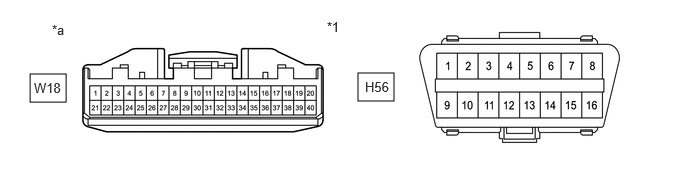
- MULTIPLEX NETWORK DOOR ECU
Refer to Terminals of ECU.
Refer to TERMINALS OF ECU [12/2019 - 11/2023]
- Disconnect the cable from the negative (-) auxiliary battery terminal.
- Disconnect the W18 multiplex network door ECU connector.
- Measure the resistance according to the value(s) in the table below.
*1 DLC3 - - *a Front view of wire harness connector
(to Multiplex Network Door ECU)- - Standard Resistance
Terminal No. (Symbol) Terminal Description Condition Specified Condition W18-39 (CANP) - W18-40 (CANN) HIGH-level CAN bus line - LOW-level CAN bus line Cable disconnected from negative (-) auxiliary battery terminal 54 to 69 Ω W18-39 (CANP) - H56-4 (CG) HIGH-level CAN bus line - Ground Cable disconnected from negative (-) auxiliary battery terminal 200 Ω or higher W18-40 (CANN) - H56-4 (CG) LOW-level CAN bus line - Ground Cable disconnected from negative (-) auxiliary battery terminal 200 Ω or higher W18-39 (CANP) - W18-20 (ECUB) HIGH-level CAN bus line - Auxiliary battery positive (+) Cable disconnected from negative (-) auxiliary battery terminal 6 kΩ or higher W18-40 (CANN) - W18-20 (ECUB) LOW-level CAN bus line - Auxiliary battery positive (+) Cable disconnected from negative (-) auxiliary battery terminal 6 kΩ or higher
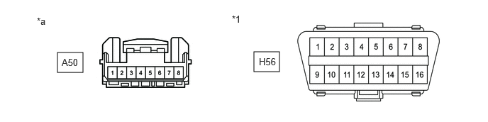
- VEHICLE APPROACHING SPEAKER CONTROLLER
Refer to Terminals of ECU.
Refer to TERMINALS OF ECU [12/2019 - 10/2022]
- Disconnect the cable from the negative (-) auxiliary battery terminal.
- Disconnect the A50 vehicle approaching speaker controller connector.
- Measure the resistance according to the value(s) in the table below.
*1 DLC3 - - *a Front view of wire harness connector
(to Vehicle Approaching Speaker Controller)- - Standard Resistance
Terminal No. (Symbol) Terminal Description Condition Specified Condition A50-3 (CANH) - A50-4 (CANL) HIGH-level CAN bus line - LOW-level CAN bus line Cable disconnected from negative (-) auxiliary battery terminal 54 to 69 Ω A50-3 (CANH) - A50-6 (GND) HIGH-level CAN bus line - Ground Cable disconnected from negative (-) auxiliary battery terminal 200 Ω or higher A50-4 (CANL) - A50-6 (GND) LOW-level CAN bus line - Ground Cable disconnected from negative (-) auxiliary battery terminal 200 Ω or higher A50-3 (CANH) - H56-16 (BAT) HIGH-level CAN bus line - Auxiliary battery positive (+) Cable disconnected from negative (-) auxiliary battery terminal 6 kΩ or higher A50-4 (CANL) - H56-16 (BAT) LOW-level CAN bus line - Auxiliary battery positive (+) Cable disconnected from negative (-) auxiliary battery terminal 6 kΩ or higher
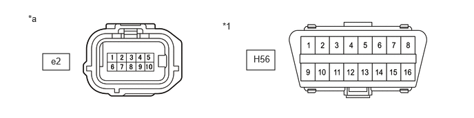
- OCCUPANT DETECTION ECU
Refer to Terminals of ECU.
Refer to TERMINALS OF ECU [12/2019 - 11/2023]
- Disconnect the cable from the negative (-) auxiliary battery terminal.
- Disconnect the e2 occupant detection ECU connector.
- Measure the resistance according to the value(s) in the table below.
*1 DLC3 - - *a Front view of wire harness connector
(to Occupant Detection ECU)- - Standard Resistance
Terminal No. (Symbol) Terminal Description Condition Specified Condition e2-5 (CANH) - e2-4 (CANL) HIGH-level CAN bus line - LOW-level CAN bus line Cable disconnected from negative (-) auxiliary battery terminal 54 to 69 Ω e2-5 (CANH) - e2-10 (GND) HIGH-level CAN bus line - Ground Cable disconnected from negative (-) auxiliary battery terminal 200 Ω or higher e2-4 (CANL) - e2-10 (GND) LOW-level CAN bus line - Ground Cable disconnected from negative (-) auxiliary battery terminal 200 Ω or higher e2-5 (CANH) - H56-16 (BAT) HIGH-level CAN bus line - Auxiliary battery positive (+) Cable disconnected from negative (-) auxiliary battery terminal 6 kΩ or higher e2-4 (CANL) - H56-16 (BAT) LOW-level CAN bus line - Auxiliary battery positive (+) Cable disconnected from negative (-) auxiliary battery terminal 6 kΩ or higher
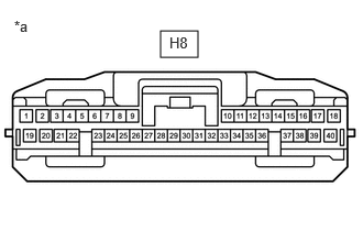
- INTEGRATION CONTROL SUB-ASSEMBLY (w/ Toyota Multi Operation Touch System)
Refer to Terminals of ECU.
Refer to TERMINALS OF ECU [12/2019 - 10/2022]
- Disconnect the cable from the negative (-) auxiliary battery terminal.
- Disconnect the H8 integration control sub-assembly connector.
- Measure the resistance according to the value(s) in the table below.
Standard Resistance
Terminal No. (Symbol) Terminal Description Condition Specified Condition H8-32 (CANP) - H8-31 (CANN) HIGH-level CAN bus line - LOW-level CAN bus line Cable disconnected from negative (-) auxiliary battery terminal 54 to 69 Ω H8-32 (CANP) - H8-20 (GND) HIGH-level CAN bus line - Ground Cable disconnected from negative (-) auxiliary battery terminal 200 Ω or higher H8-31 (CANN) - H8-20 (GND) LOW-level CAN bus line - Ground Cable disconnected from negative (-) auxiliary battery terminal 200 Ω or higher H8-32 (CANP) - H8-1 (B) HIGH-level CAN bus line - Auxiliary battery positive (+) Cable disconnected from negative (-) auxiliary battery terminal 6 kΩ or higher H8-31 (CANN) - H8-1 (B) LOW-level CAN bus line - Auxiliary battery positive (+) Cable disconnected from negative (-) auxiliary battery terminal 6 kΩ or higher *a Front view of wire harness connector
(to Integration control sub-assembly)