Disassembly [12/2019 - ]: Procedure
- REMOVE DIFFERENTIAL DISCONNECT COVER
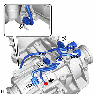
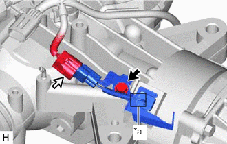
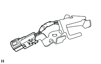
- REMOVE CLUTCH CONTROL SOLENOID WIRE
- REMOVE WIRE HARNESS CLAMP BRACKET
- REMOVE TRANSMISSION REVOLUTION SENSOR
- REMOVE TEMPERATURE SENSOR
See step 2
- REMOVE CLUTCH CONTROL SOLENOID WIRE
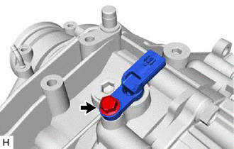
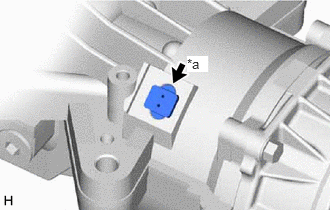
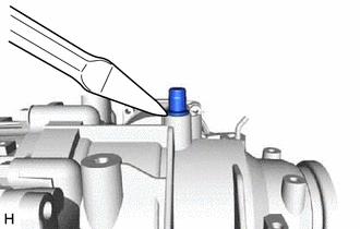
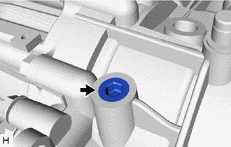
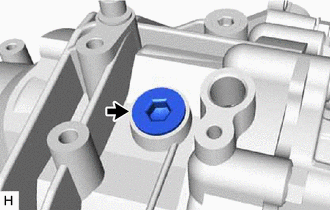
- REMOVE REAR DIFFERENTIAL BREATHER PLUG
- REMOVE REAR DIFFERENTIAL CARRIER COVER PLUG
- REMOVE REAR DIFFERENTIAL FILLER PLUG
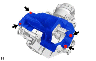
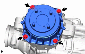
- REMOVE ELECTRO MAGNETIC CONTROL COUPLING SUB-ASSEMBLY
- Remove the 4 bolts.
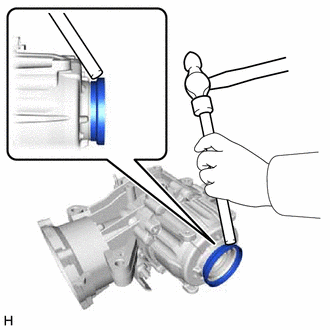
- Using a brass bar and a hammer, lightly tap the electro magnetic control coupling sub-assembly to remove it from the rear differential carrier assembly.NOTE:
- Set the brass bar on the ribbed part of the electro magnetic control coupling sub-assembly.
- Do not damage the contact surface.
HINT:
Temporarily install 2 bolts by approximately 5 or 6 threads to prevent the electro magnetic control coupling sub-assembly from falling.
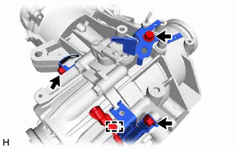
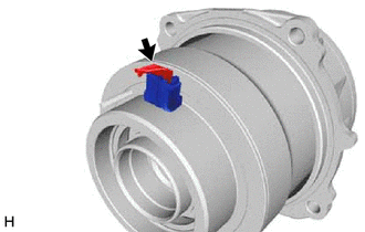
- Disconnect the connector.
- Remove the O-ring.
- Remove the 4 bolts.
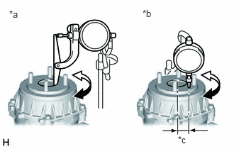
- INSPECT RUNOUT OF ELECTRO MAGNETIC CONTROL COUPLING SUB-ASSEMBLY
*a Vertical Runout *b Lateral Runout *c 45.5 mm (1.79 in.) Using a dial indicator, measure the runout of the electro magnetic control coupling sub-assembly vertical runout and lateral runout.
Maximum Runout
Item Specified Condition Vertical runout 0.070 mm (0.00276 in.) Lateral runout 0.060 mm (0.00236 in.) NOTE:Measure the runout of the electro magnetic control coupling sub-assembly horizontally at a position 45.5 mm (1.79 in.) away from the electro magnetic control coupling sub-assembly.
If the runout is greater than the maximum value, replace the electro magnetic control coupling sub-assembly.
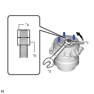
- REMOVE STUD BOLT
- Install 2 service nuts to the stud bolt.
Recommended Service Nut
Thread Diameter
10 mm (0.394 in.)
Thread Pitch
1.0 mm (0.0394 in.)
- Turn the lower nut and remove the other 3 stud bolts in the same way.
*a Upper Nut *b Lower Nut *c Turn *d Hold NOTE:Prevent foreign matter from entering the electro magnetic control coupling sub-assembly.
HINT:
Lock the lower nut using the upper nut.
If the threads of the electro magnetic control coupling sub-assembly are damaged while removing the stud bolt, replace the electro magnetic control coupling sub-assembly with a new one.
- Install 2 service nuts to the stud bolt.
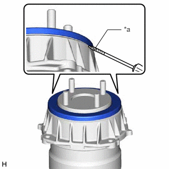
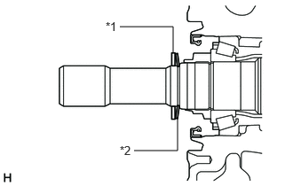
- REMOVE REAR DIFFERENTIAL DUST DEFLECTOR (for Front Side)
- Using a screwdriver, partially separate the rear differential dust deflector.
*a Protective Tape NOTE:- Separate the rear differential dust deflector to the extent the claws of SST can be inserted.
- Do not damage the end surface of the electro magnetic control coupling sub-assembly.
HINT:
Tape the screwdriver tip before use.
If the end surface of the electro magnetic control coupling sub-assembly is damaged while removing the rear differential dust deflector, replace the electro magnetic control coupling sub-assembly with a new one.
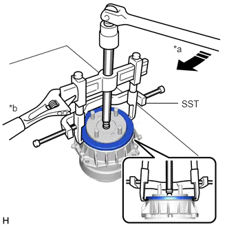
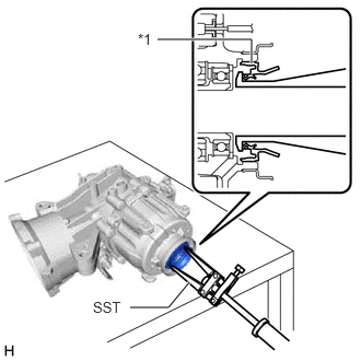
- Using SST, remove the rear differential dust deflector as shown in the illustration.
- SST: 09950-40011
- 09951-04020
- 09952-04010
- 09953-04030
- 09954-04010
- 09955-04061
- 09957-04010
- 09958-04011
*a Turn *b Hold NOTE:Before using the SST center bolt (09953-04030), apply grease to its threads and tip.
- SST: 09950-40011
- Using a screwdriver, partially separate the rear differential dust deflector.
- REMOVE TRANSMISSION COUPLING DUST SEAL
See step 7 [12/2019 - 10/2022], or see step 7 [10/2022 - 11/2023], or see step 7 [11/2023 - ]
- REMOVE CONICAL SPRING WASHER
- REMOVE REAR DIFFERENTIAL CARRIER OIL SEAL
See step 8 [12/2019 - 10/2022], or see step 8 [10/2022 - 11/2023], or see step 8 [11/2023 - ]
- REMOVE REAR DRIVE SHAFT OIL SEAL LH
- REMOVE REAR DRIVE SHAFT OIL SEAL RH
HINT:
Use the same procedure as for the LH side.
- REMOVE REAR DIFFERENTIAL DUST DEFLECTOR (for LH Side)
- REMOVE REAR DIFFERENTIAL DUST DEFLECTOR (for RH Side)
HINT:
Use the same procedure as for the LH side.