Reassembly [12/2019 - ]: Procedure
- INSTALL REAR DIFFERENTIAL DUST DEFLECTOR (for LH Side)
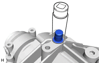
- Using a 5 mm pin punch and a hammer, install a new rear differential dust deflector to the rear differential carrier assembly.
*1 Rear Differential Dust Deflector Standard Distance (A)
-0.5 to 0.5 mm (-0.00197 to 0.0197 in.)
NOTE:- Install the rear differential dust deflector uniformly.
- Install the rear differential dust deflector straight.
- Do not damage the rear differential dust deflector.
- Do not excessively press in the rear differential dust deflector.
- Using a 5 mm pin punch and a hammer, install a new rear differential dust deflector to the rear differential carrier assembly.
- INSTALL REAR DIFFERENTIAL DUST DEFLECTOR (for RH Side)
HINT:
Perform the same procedure as for the LH side.
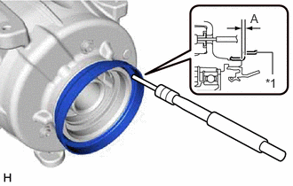
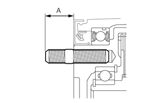
- INSTALL REAR DRIVE SHAFT OIL SEAL LH
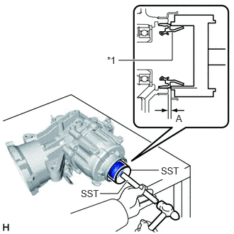
- Using SST and a hammer, install a new rear drive shaft oil seal LH to the rear differential carrier assembly.
*1 Rear Drive Shaft Oil Seal LH - SST: 09316-10010
- SST: 09950-70010
- 09951-07150
Standard Distance (A)
-0.4 to 0.4 mm (-0.00157 to 0.0157 in.)
NOTE:- Install the rear drive shaft oil seal LH uniformly.
- Install the rear drive shaft oil seal LH straight.
- Do not damage the rear drive shaft oil seal LH.
- Do not damage the rear differential dust deflector.
- Do not excessively press in the rear drive shaft oil seal LH.
- Make sure to install the rear drive shaft oil seal LH as specified, otherwise a malfunction such as an oil leak may occur.
- Apply a light coat of MP grease to the lip of the rear drive shaft oil seal LH.
- Using SST and a hammer, install a new rear drive shaft oil seal LH to the rear differential carrier assembly.
- INSTALL REAR DRIVE SHAFT OIL SEAL RH
HINT:
Use the same procedure as for the LH side.
- INSTALL REAR DIFFERENTIAL CARRIER OIL SEAL
See step 9 [12/2019 - 10/2022], or see step 9 [10/2022 - 11/2023], or see step 9 [11/2023 - ]
- INSTALL TRANSMISSION COUPLING DUST SEAL
See step 10 [12/2019 - 10/2022], or see step 10 [10/2022 - 11/2023], or see step 10 [11/2023 - ]
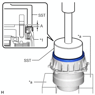
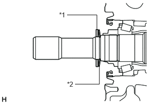
- INSTALL REAR DIFFERENTIAL DUST DEFLECTOR (for Front Side)
- Temporarily install a new rear differential dust deflector.
- Using SST, V-blocks and a press, install the rear differential dust deflector to the electro magnetic control coupling sub-assembly.
*1 Rear Differential Dust Deflector *a V-block - SST: 09223-56010
Standard Distance (A)
5.5 to 6.1 mm (0.217 to 0.240 in.)
NOTE:- Make sure that the electro magnetic control coupling sub-assembly is supported as shown in the illustration.
- Install the rear differential dust deflector uniformly.
- Install the rear differential dust deflector straight.
- Do not damage the end surface of the electro magnetic control coupling sub-assembly.
- Do not excessively press in the rear differential dust deflector.
If the end surface of the electro magnetic control coupling sub-assembly is damaged while installing the rear differential dust deflector, replace the electro magnetic control coupling sub-assembly with a new one.
- INSTALL CONICAL SPRING WASHER
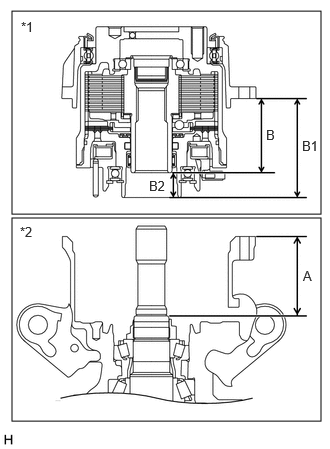
- Using a vernier caliper and precision straightedge, measure dimensions (B1) and (B2) of the electro magnetic control coupling sub-assembly.
*1 Electro Magnetic Control Coupling Sub-assembly *2 Rear Differential Carrier Assembly - Calculate dimension (B) by subtracting dimension (B2) from (B1).
HINT:
- Dimension (B) = Dimension (B1) - Dimension (B2)
- Dimension (B1) is the distance from the installation surface of the electro magnetic control coupling sub-assembly to the edge of the bearing.
- Using a vernier caliper and precision straightedge, measure dimension (A) of the rear differential carrier assembly.
HINT:
Dimension (A) is the distance from the installation surface of the rear differential carrier assembly to the edge of the differential drive pinion.
- Select a transmission coupling spacer and install it.NOTE:
Keep the transmission coupling spacer free of oil and foreign matter.
HINT:
Transmission coupling spacer thickness = Dimension (A) - Dimension (B) - 1.6
Transmission Coupling Spacer
Part No. Thickness 90564-25045 1.79 to 1.81 mm (0.0705 to 0.0713 in.) 90564-25046 1.89 to 1.91 mm (0.0744 to 0.0752 in.) 90564-25047 1.99 to 2.01 mm (0.0783 to 0.0791 in.) 90564-25048 2.09 to 2.11 mm (0.0823 to 0.0831 in.) 90564-25049 2.19 to 2.21 mm (0.0862 to 0.0870 in.) 90564-25050 2.29 to 2.31 mm (0.0902 to 0.0909 in.) 90564-25051 2.39 to 2.41 mm (0.0941 to 0.0949 in.) 90564-25052 2.49 to 2.51 mm (0.0980 to 0.0988 in.) 90564-25053 2.59 to 2.61 mm (0.1020 to 0.1028 in.) 90564-25054 2.69 to 2.71 mm (0.1059 to 0.1067 in.) 90564-25055 2.79 to 2.81 mm (0.1098 to 0.1106 in.) 90564-25056 2.89 to 2.91 mm (0.1138 to 0.1146 in.) 90564-25057 2.99 to 3.01 mm (0.1177 to 0.1185 in.) - Install the transmission coupling spacer and conical spring washer to the rear differential carrier assembly as shown in the illustration.
*1 Transmission Coupling Spacer *2 Conical Spring Washer HINT:
Make sure to install the conical spring washer with the concave side facing the front of the vehicle.
- Using a vernier caliper and precision straightedge, measure dimensions (B1) and (B2) of the electro magnetic control coupling sub-assembly.
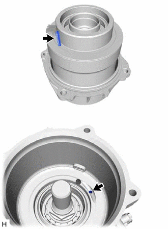
- INSTALL ELECTRO MAGNETIC CONTROL COUPLING SUB-ASSEMBLY
- Apply gear oil to a new O-ring.
- Install the O-ring to the electro magnetic control coupling sub-assembly.
- Align the pin and hole, and install the electro magnetic control coupling sub-assembly with the 4 bolts.
Torque: 19.6 N.m (200 kgf/cm, 14 ft.lbf)
NOTE:- Do not damage the rear differential carrier oil seal.
- Do not damage the contact surface of the rear differential carrier assembly and electro magnetic control coupling sub-assembly.
If the contact surface of the rear differential carrier assembly or electro magnetic control coupling sub-assembly is damaged while installing the electro magnetic control coupling sub-assembly, replace the rear differential carrier assembly or electro magnetic control coupling sub-assembly with a new one.
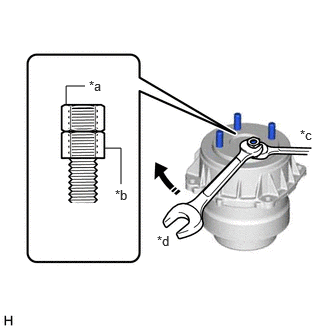
- INSTALL STUD BOLT
- Temporarily install the 4 stud bolts to the electro magnetic control coupling sub-assembly.
*a Upper Nut *b Lower Nut *c Hold *d Turn NOTE:- Make sure to install the longer bolt on the electro magnetic control coupling sub-assembly side.
- Prevent foreign matter from entering the electro magnetic control coupling sub-assembly.
- Install 2 service nuts to the stud bolt.
Recommended Service Nut
Thread Diameter
10 mm (0.394 in.)
Thread Pitch
1.0 mm (0.0394 in.)
HINT:
Lock the upper nut using the lower nut.
If the threads of the electro magnetic control coupling sub-assembly are damaged while installing the stud bolt, replace the electro magnetic control coupling sub-assembly with a new one.
- Turn the upper nut and tighten the other 3 stud bolts to the electro magnetic control coupling sub-assembly in the same way.
Torque: 9.8 N.m (100 kgf/cm, 87 in.lbf)
Standard Distance (A)
22.55 to 25.85 mm (0.888 to 1.017 in.)
- Temporarily install the 4 stud bolts to the electro magnetic control coupling sub-assembly.
- INSTALL REAR DIFFERENTIAL FILLER PLUG
- Using a 10 mm hexagon socket wrench, install a new gasket and the rear differential filler plug.
Torque: 39 N.m (398 kgf/cm, 29 ft.lbf)
- Using a 10 mm hexagon socket wrench, install a new gasket and the rear differential filler plug.
- INSTALL REAR DIFFERENTIAL CARRIER COVER PLUG
- Using an 8 mm hexagon socket wrench, install a new rear differential carrier cover plug.
Torque: 30 N.m (306 kgf/cm, 22 ft.lbf)
- Using an 8 mm hexagon socket wrench, install a new rear differential carrier cover plug.
- INSTALL REAR DIFFERENTIAL BREATHER PLUG
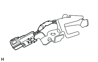
- INSTALL CLUTCH CONTROL SOLENOID WIRE
- Engage the clamp to install a new clutch control solenoid wire to the wire harness clamp bracket.
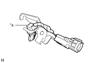
- Set the grommet to the wire harness clamp bracket as shown in the illustration.
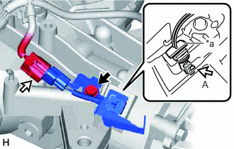
*a Grommet - Connect the 2 connectors and grommet.
*a Grommet 
Bolt 
Connector NOTE:Make sure to push down on the grommet to connect the connector (A) and to securely install the grommet.
- Install the wire harness clamp bracket with the bolt.
Torque: 5.4 N.m (55 kgf/cm, 48 in.lbf)
- Engage the clamp to install a new clutch control solenoid wire to the wire harness clamp bracket.
- INSTALL TEMPERATURE SENSOR
See step 1
- INSTALL TRANSMISSION REVOLUTION SENSOR
- Apply gear oil to a new O-ring.
- Install the O-ring to the transmission revolution sensor.
- Install the transmission revolution sensor to the rear differential carrier assembly with the bolt.
Torque: 6.5 N.m (66 kgf/cm, 58 in.lbf)
- INSTALL WIRE HARNESS CLAMP BRACKET
- Engage the clamp to connect the wire harness.NOTE:
Do not damage the wire harness.
- Install the 3 wire harness clamp brackets with 3 bolts to the rear differential carrier assembly.
Torque: 19.6 N.m (200 kgf/cm, 14 ft.lbf)
- Engage the clamp to connect the wire harness.
- INSTALL CLUTCH CONTROL SOLENOID WIRE
- Engage the 4 clamps to install the clutch control solenoid wire.
- Install the bolt.
Torque: 5.4 N.m (55 kgf/cm, 48 in.lbf)
- Connect the 4 connectors.
- INSTALL DIFFERENTIAL DISCONNECT COVER
- Install the 4 bolts and differential disconnect cover to the rear differential carrier assembly.
Torque: 6.5 N.m (66 kgf/cm, 58 in.lbf)
- Install the 4 bolts and differential disconnect cover to the rear differential carrier assembly.