DTC B1653: Driver Side Seat Position Sensor [12/2019 - 11/2023]: Procedure
- CHECK CONNECTION OF CONNECTORS
- Turn the ignition switch off.
- Disconnect the cable from the negative (-) auxiliary battery terminal.WARNING:
Wait at least 90 seconds after disconnecting the cable from the negative (-) auxiliary battery terminal to disable the SRS system.
- Check that the connectors are properly connected to the airbag sensor assembly, front seat inner belt assembly LH and seat position sensor.
OK
The connectors are properly connected.
Result
Proceed to OK NG
Result:
NG
CONNECT CONNECTORS PROPERLY
Result:
OK
See step 2
- CHECK CONNECTORS
- Disconnect the connectors from the airbag sensor assembly, front seat inner belt assembly LH and seat position sensor.
- Check that the terminals of the connectors are not deformed or damaged.
OK
The terminals are not deformed or damaged.
Result
Proceed to OK NG
Result:
NG
REPLACE NO. 2 FLOOR WIRE, FRONT SEAT NO. 2 WIRE LH OR FRONT SEAT INNER BELT ASSEMBLY LH
Result:
OK
See step 3
- CHECK WIRE HARNESS
- Connect the No. 2 floor wire and front seat No. 2 wire LH to the front seat inner belt assembly LH.
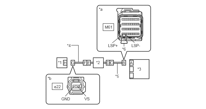
*1 Seat Position Sensor *2 Front Seat Inner Belt Assembly LH *3 Airbag Sensor Assembly *4 Front Seat No. 2 Wire LH *5 No. 2 Floor Wire *6 Service Wire *a Front view of wire harness connector
(to Airbag Sensor Assembly)*b Front view of wire harness connector
(to Seat Position Sensor) - Connect the cable to the negative (-) auxiliary battery terminal.
- Turn the ignition switch to ON.
- Measure the voltage according to the value(s) in the table below.
Standard Voltage
Tester Connection Condition Specified Condition e22-2 (VS) - Body ground Ignition switch ON Below 1 V e22-1 (GND) - Body ground Ignition switch ON Below 1 V - Turn the ignition switch off.
- Disconnect the cable from the negative (-) auxiliary battery terminal.WARNING:
Wait at least 90 seconds after disconnecting the cable from the negative (-) auxiliary battery terminal to disable the SRS system.
- Using a service wire, connect terminals 25 (LSP+) and 26 (LSP-) of connector B.NOTE:
Do not forcibly insert the service wire into the terminals of the connector when connecting the wire.
- Measure the resistance according to the value(s) in the table below.
Standard Resistance
Tester Connection Condition Specified Condition e22-2 (VS) - e22-1 (GND) Always Below 1 Ω - Disconnect the service wire from connector B.
- Measure the resistance according to the value(s) in the table below.
Standard Resistance
Tester Connection Condition Specified Condition e22-2 (VS) - e22-1 (GND) Always 1 MΩ or higher e22-2 (VS) - Body ground Always 1 MΩ or higher e22-1 (GND) - Body ground Always 1 MΩ or higher Result
Proceed to OK NG
Result:
NG
See step 6
Result:
OK
See step 4
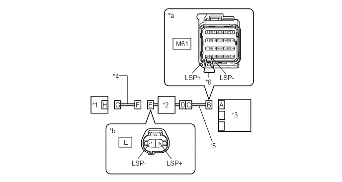
- Connect the No. 2 floor wire and front seat No. 2 wire LH to the front seat inner belt assembly LH.
- CHECK DTC
- Connect the connectors to the airbag sensor assembly and seat position sensor.
*1 Seat Position Sensor *2 Front Seat Inner Belt Assembly LH *3 Airbag Sensor Assembly - Connect the cable to the negative (-) auxiliary battery terminal.
- Turn the ignition switch to ON, and wait for at least 60 seconds.
- Clear the DTCs stored in memory.
Body Electrical > SRS Airbag > Clear DTCs
- Turn the ignition switch off.
- Turn the ignition switch to ON, and wait for at least 60 seconds.
- Check for DTCs.
Body Electrical > SRS Airbag > Trouble Codes
OK
DTC B1653 is not output.
HINT:
Codes other than DTC B1653 may be output at this time, but they are not related to this check.
Result
Proceed to OK NG
Result:
OK
USE SIMULATION METHOD TO CHECK. Refer to HOW TO PROCEED WITH TROUBLESHOOTING [12/2019 - ]
Result:
NG
See step 5
- Connect the connectors to the airbag sensor assembly and seat position sensor.
- CHECK AIRBAG SENSOR ASSEMBLY
- Turn the ignition switch off.
*1 Seat Position Sensor *2 Front Seat Inner Belt Assembly LH *3 Airbag Sensor Assembly - Disconnect the cable from the negative (-) auxiliary battery terminal.WARNING:
Wait at least 90 seconds after disconnecting the cable from the negative (-) auxiliary battery terminal to disable the SRS system.
- Replace the airbag sensor assembly with a known good one.
Refer to REMOVAL [12/2019 - 10/2022] , or refer to REMOVAL [10/2022 - 11/2023]
HINT:
Perform the following inspection using known good parts from another vehicle if possible.
- Connect the cable to the negative (-) auxiliary battery terminal.
- Turn the ignition switch to ON, and wait for at least 60 seconds.
- Check for DTCs.
Body Electrical > SRS Airbag > Trouble Codes
OK
DTC B1653 is not output.
HINT:
Codes other than DTC B1653 may be output at this time, but they are not related to this check.
- Turn the ignition switch off.
- Disconnect the cable from the negative (-) auxiliary battery terminal.WARNING:
Wait at least 90 seconds after disconnecting the cable from the negative (-) auxiliary battery terminal to disable the SRS system.
- Restore the airbag sensor assembly that was installed for testing to its original location.
Refer to REMOVAL [12/2019 - 10/2022] , or refer to REMOVAL [10/2022 - 11/2023]
Result
Proceed to OK NG
Result:
OK
REPLACE AIRBAG SENSOR ASSEMBLY. Refer to REMOVAL [12/2019 - 10/2022] , or refer to REMOVAL [10/2022 - 11/2023]
Result:
NG
REPLACE SEAT POSITION SENSOR (SEPARATE TYPE FRONT SEAT CUSHION SPRING ASSEMBLY LH). Refer to REMOVAL [12/2019 - 10/2021] , or refer to REMOVAL [10/2021 - 10/2022] , or refer to REMOVAL [10/2022 - 11/2023]
- Turn the ignition switch off.
- CHECK WIRE HARNESS
- Disconnect the front seat No. 2 wire LH connector from the front seat inner belt assembly LH.
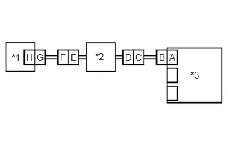
*1 Seat Position Sensor *2 Front Seat Inner Belt Assembly LH *3 Airbag Sensor Assembly *4 Front Seat No. 2 Wire LH *5 No. 2 Floor Wire *6 Service Wire *a Front view of wire harness connector
(to Airbag Sensor Assembly)*b Front view of wire harness connector
(to Front Seat No. 2 Wire LH) - Connect the cable to the negative (-) auxiliary battery terminal.
- Turn the ignition switch to ON.
- Measure the voltage according to the value(s) in the table below.
Standard Voltage
Tester Connection Condition Specified Condition E-2 (LSP+) - Body ground Ignition switch ON Below 1 V E-1 (LSP-) - Body ground Ignition switch ON Below 1 V - Turn the ignition switch off.
- Disconnect the cable from the negative (-) auxiliary battery terminal.WARNING:
Wait at least 90 seconds after disconnecting the cable from the negative (-) auxiliary battery terminal to disable the SRS system.
- Using a service wire, connect terminals 25 (LSP+) and 26 (LSP-) of connector B.NOTE:
Do not forcibly insert the service wire into the terminals of the connector when connecting the wire.
- Measure the resistance according to the value(s) in the table below.
Standard Resistance
Tester Connection Condition Specified Condition E-2 (LSP+) - E-1 (LSP-) Always Below 1 Ω - Disconnect the service wire from connector B.
- Measure the resistance according to the value(s) in the table below.
Standard Resistance
Tester Connection Condition Specified Condition E-2 (LSP+) - E-1 (LSP-) Always 1 MΩ or higher E-2 (LSP+) - Body ground Always 1 MΩ or higher E-1 (LSP-) - Body ground Always 1 MΩ or higher Result
Proceed to OK NG
Result:
OK
REPLACE FRONT SEAT NO. 2 WIRE LH
Result:
NG
See step 7
- Disconnect the front seat No. 2 wire LH connector from the front seat inner belt assembly LH.
- CHECK NO. 2 FLOOR WIRE
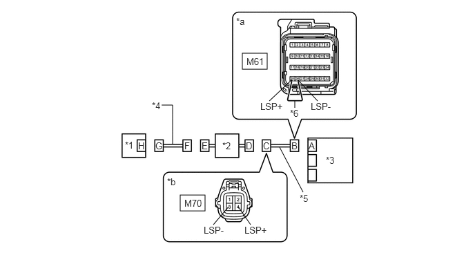
- Disconnect the No. 2 floor wire connector from the front seat inner belt assembly LH.
*1 Seat Position Sensor *2 Front Seat Inner Belt Assembly LH *3 Airbag Sensor Assembly *4 Front Seat No. 2 Wire LH *5 No. 2 Floor Wire *6 Service Wire *a Front view of wire harness connector
(to Airbag Sensor Assembly)*b Front view of wire harness connector
(to Front Seat Inner Belt Assembly LH) - Connect the cable to the negative (-) auxiliary battery terminal.
- Turn the ignition switch to ON.
- Measure the voltage according to the value(s) in the table below.
Standard Voltage
Tester Connection Condition Specified Condition M70-4 (LSP+) - Body ground Ignition switch ON Below 1 V M70-3 (LSP-) - Body ground Ignition switch ON Below 1 V - Turn the ignition switch off.
- Disconnect the cable from the negative (-) auxiliary battery terminal.WARNING:
Wait at least 90 seconds after disconnecting the cable from the negative (-) auxiliary battery terminal to disable the SRS system.
- Using a service wire, connect terminals 25 (LSP+) and 26 (LSP-) of connector B.NOTE:
Do not forcibly insert the service wire into the terminals of the connector when connecting the wire.
- Measure the resistance according to the value(s) in the table below.
Standard Resistance
Tester Connection Condition Specified Condition M70-4 (LSP+) - M70-3 (LSP-) Always Below 1 Ω - Disconnect the service wire from connector B.
- Measure the resistance according to the value(s) in the table below.
Standard Resistance
Tester Connection Condition Specified Condition M70-4 (LSP+) - M70-3 (LSP-) Always 1 MΩ or higher M70-4 (LSP+) - Body ground Always 1 MΩ or higher M70-3 (LSP-) - Body ground Always 1 MΩ or higher Result
Proceed to OK NG
Result:
OK
REPLACE FRONT SEAT INNER BELT ASSEMBLY LH. Refer to REMOVAL [12/2019 - 10/2022] , or refer to REMOVAL [10/2022 - 11/2023]
Result:
NG
REPLACE NO. 2 FLOOR WIRE
- Disconnect the No. 2 floor wire connector from the front seat inner belt assembly LH.