DTC B1660: P Seat Airbag Active Mode Indicator [12/2019 - 10/2022]: Procedure
- CHECK PASSENGER AIRBAG ON/OFF INDICATOR CONDITION
- Turn the ignition switch to ON.
- Check the passenger airbag ON/OFF indicator operation.
HINT:
Refer to the normal condition of the passenger airbag ON/OFF indicator.
Refer to OPERATION CHECK [12/2019 - 10/2022]
Result
Result Proceed to Passenger airbag ON/OFF indicator illumination is always on. A Passenger airbag ON/OFF indicator illumination is always off. B
Result:
B
See step 8
Result:
A
See step 2
- CHECK CONNECTION OF CONNECTORS
- Turn the ignition switch off.
- Disconnect the cable from the negative (-) auxiliary battery terminal.WARNING:
Wait at least 90 seconds after disconnecting the cable from the negative (-) auxiliary battery terminal to disable the SRS system.
- Check that the connectors are properly connected to the airbag sensor assembly, telltale light assembly and instrument panel junction block assembly.
OK
The connectors are properly connected.
Result
Proceed to OK NG
Result:
NG
CONNECT CONNECTORS PROPERLY
Result:
OK
See step 3
- CHECK CONNECTORS
- Disconnect the connectors from the airbag sensor assembly, telltale light assembly and instrument panel junction block assembly.
- Check that the terminals of the connectors are not deformed or damaged.
OK
The terminals are not deformed or damaged.
Result
Proceed to OK NG
Result:
NG
REPLACE INSTRUMENT PANEL WIRE
Result:
OK
See step 4
- CHECK PASSENGER AIRBAG ON/OFF INDICATOR CONDITION
- Connect the connector to the telltale light assembly and instrument panel junction block assembly.
- Connect the cable to the negative (-) auxiliary battery terminal.
- Turn the ignition switch to ON.
- Check the passenger airbag ON/OFF indicator operation.
OK
The passenger airbag ON/OFF indicator does not come on.
Result
Proceed to OK NG
Result:
NG
See step 6
Result:
OK
See step 5
- CHECK DTC
- Turn the ignition switch off.
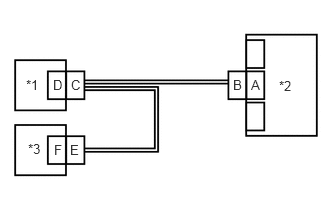
*1 Instrument Panel Junction Block Assembly *2 Airbag Sensor Assembly *3 Telltale Light Assembly - Disconnect the cable from the negative (-) auxiliary battery terminal.WARNING:
Wait at least 90 seconds after disconnecting the cable from the negative (-) auxiliary battery terminal to disable the SRS system.
- Connect the connector to the airbag sensor assembly.
- Connect the cable to the negative (-) auxiliary battery terminal.
- Turn the ignition switch to ON, and wait for at least 60 seconds.
- Clear the DTCs stored in memory.
Body Electrical > SRS Airbag > Clear DTCs
- Turn the ignition switch off.
- Turn the ignition switch to ON, and wait for at least 60 seconds.
- Check for DTCs.
Body Electrical > SRS Airbag > Trouble Codes
OK
DTC B1660 is not output.
HINT:
Codes other than DTC B1660 may be output at this time, but they are not related to this check.
Result
Proceed to OK NG
Result:
OK
USE SIMULATION METHOD TO CHECK. Refer to HOW TO PROCEED WITH TROUBLESHOOTING [12/2019 - ]
Result:
NG
REPLACE AIRBAG SENSOR ASSEMBLY. Refer to REMOVAL [12/2019 - 10/2022]
- Turn the ignition switch off.
- CHECK WIRE HARNESS
- Turn the ignition switch off.
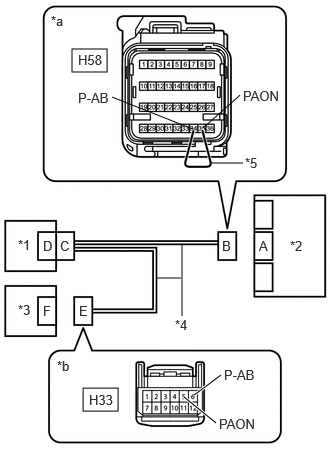
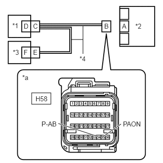
*1 Instrument Panel Junction Block Assembly *2 Airbag Sensor Assembly *3 Telltale Light Assembly *4 Instrument Panel Wire *5 Service Wire *a Front view of wire harness connector
(to Airbag Sensor Assembly)*b Front view of wire harness connector
(to Telltale Light Assembly) - Disconnect the cable from the negative (-) auxiliary battery terminal.WARNING:
Wait at least 90 seconds after disconnecting the cable from the negative (-) auxiliary battery terminal to disable the SRS system.
- Disconnect the connector from the telltale light assembly.
- Connect the cable to the negative (-) auxiliary battery terminal.
- Turn the ignition switch to ON.
- Measure the voltage according to the value(s) in the table below.
Standard Voltage
Tester Connection Condition Specified Condition H33-5 (PAON) - Body ground Ignition switch ON Below 1 V H33-6 (P-AB) - Body ground Ignition switch ON Below 1 V - Turn the ignition switch off.
- Disconnect the cable from the negative (-) auxiliary battery terminal.WARNING:
Wait at least 90 seconds after disconnecting the cable from the negative (-) auxiliary battery terminal to disable the SRS system.
- Using a service wire, connect terminals 35 (PAON) and 34 (P-AB) of connector B.NOTE:
Do not forcibly insert the service wire into the terminals of the connector when connecting the wire.
- Measure the resistance according to the value(s) in the table below.
Standard Resistance
Tester Connection Condition Specified Condition H33-5 (PAON) - H33-6 (P-AB) Always Below 1 Ω - Disconnect the service wire from connector B.
- Measure the resistance according to the value(s) in the table below.
Standard Resistance
Tester Connection Condition Specified Condition H33-5 (PAON) - H33-6 (P-AB) Always 1 MΩ or higher H33-5 (PAON) - Body ground Always 1 MΩ or higher H33-6 (P-AB) - Body ground Always 1 MΩ or higher Result
Proceed to OK NG
Result:
OK
REPLACE TELLTALE LIGHT ASSEMBLY. Refer to REMOVAL [12/2019 - 10/2022]
Result:
NG
See step 7
- Turn the ignition switch off.
- CHECK INSTRUMENT PANEL WIRE
- Disconnect the connector from the instrument panel junction block assembly.
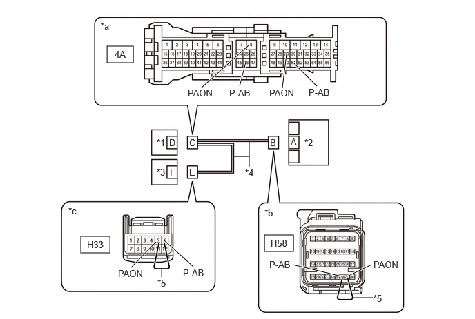
*1 Instrument Panel Junction Block Assembly *2 Airbag Sensor Assembly *3 Telltale Light Assembly *4 Instrument Panel Wire *5 Service Wire - - *a Front view of wire harness connector
(to Instrument Panel Junction Block Assembly)*b Front view of wire harness connector
(to Airbag Sensor Assembly)*c Front view of wire harness connector
(to Telltale Light Assembly)- - - Using a service wire, connect terminals 35 (PAON) and 34 (P-AB) of connector B.NOTE:
Do not forcibly insert the service wire into the terminals of the connector when connecting the wire.
- Measure the resistance according to the value(s) in the table below.
Standard Resistance
Tester Connection Condition Specified Condition 4A-8 (PAON) - 4A-46 (P-AB) Always Below 1 Ω - Disconnect the service wire from connector B.
- Using a service wire, connect terminals 5 (PAON) and 6 (P-AB) of connector E.NOTE:
Do not forcibly insert the service wire into the terminals of the connector when connecting the wire.
- Measure the resistance according to the value(s) in the table below.
Standard Resistance
Tester Connection Condition Specified Condition 4A-29 (PAON) - 4A-51 (P-AB) Always Below 1 Ω - Disconnect the service wire from connector E.
- Measure the resistance according to the value(s) in the table below.
Standard Resistance
Tester Connection Condition Specified Condition 4A-8 (PAON) - Body ground or other terminals Always 1 MΩ or higher 4A-29 (PAON) - Body ground or other terminals Always 1 MΩ or higher 4A-46 (P-AB) - Body ground or other terminals Always 1 MΩ or higher 4A-51 (P-AB) - Body ground or other terminals Always 1 MΩ or higher Result
Proceed to OK NG
Result:
OK
REPLACE INSTRUMENT PANEL JUNCTION BLOCK ASSEMBLY
Result:
NG
REPLACE INSTRUMENT PANEL WIRE
- Disconnect the connector from the instrument panel junction block assembly.
- CHECK CONNECTION OF CONNECTORS
- Turn the ignition switch off.
- Disconnect the cable from the negative (-) auxiliary battery terminal.WARNING:
Wait at least 90 seconds after disconnecting the cable from the negative (-) auxiliary battery terminal to disable the SRS system.
- Check that the connectors are properly connected to the airbag sensor assembly, telltale light assembly and instrument panel junction block assembly.
OK
The connectors are properly connected.
Result
Proceed to OK NG
Result:
NG
CONNECT CONNECTORS PROPERLY
Result:
OK
See step 9
- CHECK CONNECTORS
- Disconnect the connectors from the airbag sensor assembly, telltale light assembly and instrument panel junction block assembly.
- Check that the terminals of the connectors are not deformed or damaged.
OK
The terminals are not deformed or damaged.
Result
Proceed to OK NG
Result:
NG
REPLACE INSTRUMENT PANEL WIRE
Result:
OK
See step 10
- CHECK WIRE HARNESS
- Connect the connector to the instrument panel junction block assembly.
*1 Instrument Panel Junction Block Assembly *2 Airbag Sensor Assembly *3 Telltale Light Assembly *4 Instrument Panel Wire *5 Service Wire *a Front view of wire harness connector
(to Airbag Sensor Assembly)*b Front view of wire harness connector
(to Telltale Light Assembly) - Connect the cable to the negative (-) auxiliary battery terminal.
- Turn the ignition switch to ON.
- Measure the voltage according to the value(s) in the table below.
Standard Voltage
Tester Connection Condition Specified Condition H33-5 (PAON) - Body ground Ignition switch ON Below 1 V H33-6 (P-AB) - Body ground Ignition switch ON Below 1 V - Turn the ignition switch off.
- Disconnect the cable from the negative (-) auxiliary battery terminal.WARNING:
Wait at least 90 seconds after disconnecting the cable from the negative (-) auxiliary battery terminal to disable the SRS system.
- Using a service wire, connect terminals 35 (PAON) and 34 (P-AB) of connector B.NOTE:
Do not forcibly insert the service wire into the terminals of the connector when connecting the wire.
- Measure the resistance according to the value(s) in the table below.
Standard Resistance
Tester Connection Condition Specified Condition H33-5 (PAON) - H33-6 (P-AB) Always Below 1 Ω - Disconnect the service wire from connector B.
- Measure the resistance according to the value(s) in the table below.
Standard Resistance
Tester Connection Condition Specified Condition H33-5 (PAON) - H33-6 (P-AB) Always 1 MΩ or higher H33-5 (PAON) - Body ground Always 1 MΩ or higher H33-6 (P-AB) - Body ground Always 1 MΩ or higher Result
Proceed to OK NG
Result:
NG
See step 14
Result:
OK
See step 11
- Connect the connector to the instrument panel junction block assembly.
- CHECK PASSENGER AIRBAG ON/OFF INDICATOR (SOURCE VOLTAGE)
- Connect the cable to the negative (-) auxiliary battery terminal.
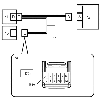
*1 Instrument Panel Junction Block Assembly *2 Airbag Sensor Assembly *3 Telltale Light Assembly *4 Instrument Panel Wire *a Front view of wire harness connector
(to Telltale Light Assembly) - Turn the ignition switch to ON.
- Measure the voltage according to the value(s) in the table below.
Standard Voltage
Tester Connection Condition Specified Condition H33-1 (IG+) - Body ground Ignition switch ON 11 to 14 V - Turn the ignition switch off.
- Disconnect the cable from the negative (-) auxiliary battery terminal.WARNING:
Wait at least 90 seconds after disconnecting the cable from the negative (-) auxiliary battery terminal to disable the SRS system.
Result
Proceed to OK NG
Result:
NG
REPLACE WIRE HARNESS OR AUXILIARY BATTERY
Result:
OK
See step 12
- Connect the cable to the negative (-) auxiliary battery terminal.
- CHECK PASSENGER AIRBAG ON/OFF INDICATOR
- Connect the connector to the telltale light assembly.
*1 Instrument Panel Junction Block Assembly *2 Airbag Sensor Assembly *3 Telltale Light Assembly *4 Instrument Panel Wire *a Front view of wire harness connector
(to Airbag Sensor Assembly) - Connect the cable to the negative (-) auxiliary battery terminal.
- Turn the ignition switch to ON.
- Check the passenger airbag ON/OFF indicator according to the conditions in the table below.
OK
Terminal Connection Condition Specified Condition H58-35 (PAON) - Body ground Ignition switch ON "ON" comes on H58-34 (P-AB) - Body ground Ignition switch ON "OFF" comes on - Turn the ignition switch off.
- Disconnect the cable from the negative (-) auxiliary battery terminal.WARNING:
Wait at least 90 seconds after disconnecting the cable from the negative (-) auxiliary battery terminal to disable the SRS system.
Result
Proceed to OK NG
Result:
NG
REPLACE TELLTALE LIGHT ASSEMBLY. Refer to REMOVAL [12/2019 - 10/2022]
Result:
OK
See step 13
- Connect the connector to the telltale light assembly.
- CHECK DTC
- Connect the connector to the airbag sensor assembly.
*1 Instrument Panel Junction Block Assembly *2 Airbag Sensor Assembly *3 Telltale Light Assembly - Connect the cable to the negative (-) auxiliary battery terminal.
- Turn the ignition switch to ON, and wait for at least 60 seconds.
- Clear the DTCs stored in memory.
Body Electrical > SRS Airbag > Clear DTCs
- Turn the ignition switch off.
- Turn the ignition switch to ON, and wait for at least 60 seconds.
- Check for DTCs.
Body Electrical > SRS Airbag > Trouble Codes
OK
DTC B1660 is not output.
HINT:
Codes other than DTC B1660 may be output at this time, but they are not related to this check.
Result
Proceed to OK NG
Result:
OK
USE SIMULATION METHOD TO CHECK. Refer to HOW TO PROCEED WITH TROUBLESHOOTING [12/2019 - ]
Result:
NG
REPLACE AIRBAG SENSOR ASSEMBLY. Refer to REMOVAL [12/2019 - 10/2022]
- Connect the connector to the airbag sensor assembly.
- CHECK INSTRUMENT PANEL WIRE
- Disconnect the connector from the instrument panel junction block assembly.
*1 Instrument Panel Junction Block Assembly *2 Airbag Sensor Assembly *3 Telltale Light Assembly *4 Instrument Panel Wire *5 Service Wire - - *a Front view of wire harness connector
(to Instrument Panel Junction Block Assembly)*b Front view of wire harness connector
(to Airbag Sensor Assembly)*c Front view of wire harness connector
(to Telltale Light Assembly)- - - Using a service wire, connect terminals 35 (PAON) and 34 (P-AB) of connector B.NOTE:
Do not forcibly insert the service wire into the terminals of the connector when connecting the wire.
- Measure the resistance according to the value(s) in the table below.
Standard Resistance
Tester Connection Condition Specified Condition 4A-8 (PAON) - 4A-46 (P-AB) Always Below 1 Ω - Disconnect the service wire from connector B.
- Using a service wire, connect terminals 5 (PAON) and 6 (P-AB) of connector E.NOTE:
Do not forcibly insert the service wire into the terminals of the connector when connecting the wire.
- Measure the resistance according to the value(s) in the table below.
Standard Resistance
Tester Connection Condition Specified Condition 4A-29 (PAON) - 4A-51 (P-AB) Always Below 1 Ω - Disconnect the service wire from connector E.
- Measure the resistance according to the value(s) in the table below.
Standard Resistance
Tester Connection Condition Specified Condition 4A-8 (PAON) - Body ground or other terminals Always 1 MΩ or higher 4A-29 (PAON) - Body ground or other terminals Always 1 MΩ or higher 4A-46 (P-AB) - Body ground or other terminals Always 1 MΩ or higher 4A-51 (P-AB) - Body ground or other terminals Always 1 MΩ or higher Result
Proceed to OK NG
Result:
OK
REPLACE INSTRUMENT PANEL JUNCTION BLOCK ASSEMBLY
Result:
NG
REPLACE INSTRUMENT PANEL WIRE
- Disconnect the connector from the instrument panel junction block assembly.