DTC B00B5-00: Driver Seat Track Position Restraints Sensor Circuit Undetermined Failure [11/2023 - ]: Procedure
- CHECK CONNECTION OF CONNECTORS
Pre-procedure1
- Turn the ignition switch off.
- Disconnect the cable from the negative (-) auxiliary battery terminal, and wait for at least 60 seconds.
Procedure1
- Check that the connectors are properly connected to the airbag sensor assembly and seat position sensor (separate type front seat cushion spring assembly LH).
OK
The connectors are properly connected.
Result
Proceed to OK NG Post-procedure1
- None
Result:
NG
CONNECT CONNECTORS PROPERLY
Result:
OK
See step 2
- CHECK CONNECTORS
Pre-procedure1
- Disconnect the airbag sensor assembly connector.
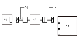
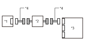
*1 Seat Position Sensor (Separate Type Front Seat Cushion Spring Assembly LH) *2 Front Seat Inner Belt Assembly LH *3 Airbag Sensor Assembly *4 Wire Harness - Disconnect the seat position sensor connector.
Procedure1
- Check that the terminals of the connectors are not deformed or damaged.
OK
The terminals are not deformed or damaged.
Result
Proceed to OK NG Post-procedure1
- None
Result:
NG
REPAIR OR REPLACE HARNESS OR CONNECTOR
Result:
OK
See step 3
- Disconnect the airbag sensor assembly connector.
- INSPECT SEAT POSITION SENSOR (SEPARATE TYPE FRONT SEAT CUSHION SPRING ASSEMBLY LH)
Pre-procedure1
- Remove the seat position sensor (separate type front seat cushion spring assembly LH).
Refer to REMOVAL [11/2023 - ]
Procedure1
- Inspect the seat position sensor.
- Remove and reinsert the metal plate into the slit of the seat position sensor and measure the current value.
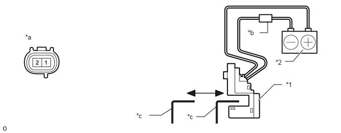
*1 Seat Position Sensor *2 Auxiliary battery *a Component without harness connected
(Seat Position Sensor (Separate Type Front Seat Cushion Spring Assembly LH))*b Tester *c Metal plate - - Standard Current
Tester Connection Condition Specified Condition Tester positive (+) - 1
Tester negative (-) - Auxiliary battery negative (-)Metal plate in slit 4.7 to 7.3 mA Metal plate not in slit 11.4 to 17.9 mA Result
Proceed to OK NG
Post-procedure1
- Remove and reinsert the metal plate into the slit of the seat position sensor and measure the current value.
- None
Result:
NG
REPLACE SEAT POSITION SENSOR (SEPARATE TYPE FRONT SEAT CUSHION SPRING ASSEMBLY LH). Refer to REMOVAL [11/2023 - ]
Result:
OK
See step 4
- Remove the seat position sensor (separate type front seat cushion spring assembly LH).
- CHECK SEAT POSITION SENSOR CIRCUIT (CHECK FOR OPEN IN THE CIRCUIT)
Pre-procedure1
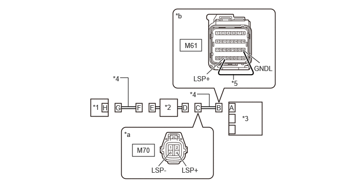
- Using a service wire, connect terminals 27 (LSP+) and 24 (GNDL) of connector B.NOTE:
Do not forcibly insert the service wire into the terminals of the connector when connecting a service wire.
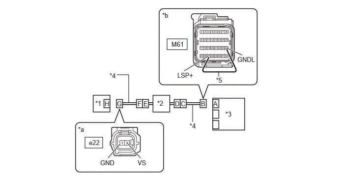
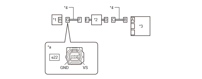
*1 Seat Position Sensor (Separate Type Front Seat Cushion Spring Assembly LH) *2 Front Seat Inner Belt Assembly LH *3 Airbag Sensor Assembly *4 Wire Harness *5 Service Wire - - *a Front view of wire harness connector
(to Seat Position Sensor (Separate Type Front Seat Cushion Spring Assembly LH))*b Front view of wire harness connector
(to Airbag Sensor Assembly)Procedure1
- Measure the resistance according to the value(s) in the table below.
Standard Resistance
Tester Connection Condition Specified Condition e22-1 (GND) - e22-2 (VS) Always Below 1 Ω Result
Proceed to OK NG Post-procedure1
- Disconnect the service wire from connector B.
Result:
NG
See step 17
Result:
OK
See step 5
- Using a service wire, connect terminals 27 (LSP+) and 24 (GNDL) of connector B.
- CHECK SEAT POSITION SENSOR CIRCUIT (CHECK FOR SHORT TO GROUND IN THE CIRCUIT)
- Measure the resistance according to the value(s) in the table below.
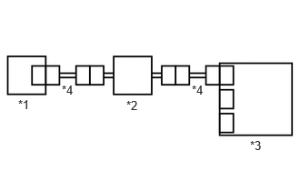
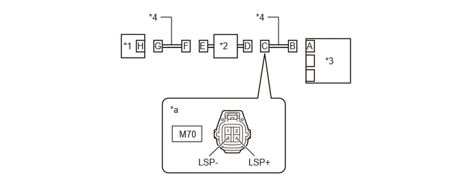
*1 Seat Position Sensor (Separate Type Front Seat Cushion Spring Assembly LH) *2 Front Seat Inner Belt Assembly LH *3 Airbag Sensor Assembly *4 Wire Harness *a Front view of wire harness connector
(to Seat Position Sensor (Separate Type Front Seat Cushion Spring Assembly LH))- - Standard Resistance
Tester Connection Condition Specified Condition e22-1 (GND) - Body ground Always 1 MΩ or higher e22-2 (VS) - Body ground Always 1 MΩ or higher Result
Proceed to OK NG
Result:
NG
See step 13
Result:
OK
See step 6
- Measure the resistance according to the value(s) in the table below.
- CHECK SEAT POSITION SENSOR CIRCUIT (CHECK FOR SHORT TO +B IN THE CIRCUIT)
Pre-procedure1
- Connect the cable to the negative (-) auxiliary battery terminal, and wait for at least 2 seconds.
- Turn the ignition switch to ON.
Procedure1
- Measure the voltage according to the value(s) in the table below.
*1 Seat Position Sensor (Separate Type Front Seat Cushion Spring Assembly LH) *2 Front Seat Inner Belt Assembly LH *3 Airbag Sensor Assembly *4 Wire Harness *a Front view of wire harness connector
(to Seat Position Sensor (Separate Type Front Seat Cushion Spring Assembly LH))- - Standard Voltage
Tester Connection Condition Specified Condition e22-1 (GND) - Body ground Ignition switch ON Below 1 V e22-2 (VS) - Body ground Ignition switch ON Below 1 V Result
Proceed to OK NG Post-procedure1
- Turn the ignition switch off.
- Disconnect the cable from the negative (-) auxiliary battery terminal, and wait for at least 60 seconds.
Result:
NG
See step 9
Result:
OK
See step 7
- CLEAR DTC
Pre-procedure1
- Connect the airbag sensor assembly connector.
*1 Seat Position Sensor (Separate Type Front Seat Cushion Spring Assembly LH) *2 Front Seat Inner Belt Assembly LH *3 Airbag Sensor Assembly *4 Wire Harness - Connect the seat position sensor (separate type front seat cushion spring assembly LH) connector.
- Connect the cable to the negative (-) auxiliary battery terminal, and wait for at least 2 seconds.
- Turn the ignition switch to ON, and wait for at least 60 seconds.
Procedure1
- Clear the DTCs stored in memory.
Body Electrical > SRS Airbag > Clear DTCs
Result
Proceed to NEXT Post-procedure1
- Turn the ignition switch off.
Result:
NEXT
See step 8
- Connect the airbag sensor assembly connector.
- CHECK DTC
Pre-procedure1
- Turn the ignition switch to ON, and wait for at least 60 seconds.
Procedure1
- Check for DTCs.
Body Electrical > SRS Airbag > Trouble Codes
Result
Result Proceed to B00B5-00 is output A B00B5-00 is not output B HINT:
Codes other than DTC B00B5-00 may be output at this time, but they are not related to this check.
Post-procedure1
- None
Result:
A
REPLACE AIRBAG SENSOR ASSEMBLY. Refer to REMOVAL [11/2023 - ]
Result:
B
USE SIMULATION METHOD TO CHECK. Refer to HOW TO PROCEED WITH TROUBLESHOOTING [12/2019 - ]
- Turn the ignition switch to ON, and wait for at least 60 seconds.
- CHECK CONNECTION OF CONNECTORS
- Check that the connectors are properly connected to the front seat inner belt assembly LH.
OK
The connectors are properly connected.
Result
Proceed to OK NG
Result:
NG
CONNECT CONNECTORS PROPERLY
Result:
OK
See step 10
- Check that the connectors are properly connected to the front seat inner belt assembly LH.
- CHECK CONNECTORS
Pre-procedure1
- Disconnect the front seat inner belt assembly LH connector.
*1 Seat Position Sensor (Separate Type Front Seat Cushion Spring Assembly LH) *2 Front Seat Inner Belt Assembly LH *3 Airbag Sensor Assembly *4 Wire Harness Procedure1
- Check that the terminals of the connectors are not deformed or damaged.
OK
The terminals are not deformed or damaged.
Result
Proceed to OK NG Post-procedure1
- None
Result:
NG
REPLACE FRONT SEAT INNER BELT ASSEMBLY LH OR REPAIR OR REPLACE HARNESS OR CONNECTOR
Result:
OK
See step 11
- Disconnect the front seat inner belt assembly LH connector.
- CHECK HARNESS AND CONNECTOR (SEAT POSITION SENSOR - FRONT SEAT INNER BELT ASSEMBLY LH)
Pre-procedure1
- Connect the cable to the negative (-) auxiliary battery terminal, and wait for at least 2 seconds.
- Turn the ignition switch to ON.
Procedure1
- Measure the voltage according to the value(s) in the table below.
*1 Seat Position Sensor (Separate Type Front Seat Cushion Spring Assembly LH) *2 Front Seat Inner Belt Assembly LH *3 Airbag Sensor Assembly *4 Wire Harness *a Front view of wire harness connector
(to Seat Position Sensor (Separate Type Front Seat Cushion Spring Assembly LH))- - Standard Voltage
Tester Connection Condition Specified Condition e22-2 (VS) - Body ground Ignition switch ON Below 1 V e22-1 (GND) - Body ground Ignition switch ON Below 1 V Result
Proceed to OK NG Post-procedure1
- Turn the ignition switch off.
- Disconnect the cable from the negative (-) auxiliary battery terminal, and wait for at least 60 seconds.
Result:
NG
REPAIR OR REPLACE HARNESS OR CONNECTOR
Result:
OK
See step 12
- CHECK HARNESS AND CONNECTOR (FRONT SEAT INNER BELT ASSEMBLY LH - AIRBAG SENSOR ASSEMBLY)
Pre-procedure1
- Connect the cable to the negative (-) auxiliary battery terminal, and wait for at least 2 seconds.
- Turn the ignition switch to ON.
Procedure1
- Measure the voltage according to the value(s) in the table below.
*1 Seat Position Sensor (Separate Type Front Seat Cushion Spring Assembly LH) *2 Front Seat Inner Belt Assembly LH *3 Airbag Sensor Assembly *4 Wire Harness *a Front view of wire harness connector
(to Front Seat Inner Belt Assembly LH)- - Standard Voltage
Tester Connection Condition Specified Condition M70-4 (LSP+) - Body ground Ignition switch ON Below 1 V M70-3 (LSP-) - Body ground Ignition switch ON Below 1 V Result
Proceed to OK NG Post-procedure1
- Turn the ignition switch off.
- Disconnect the cable from the negative (-) auxiliary battery terminal, and wait for at least 60 seconds.
Result:
OK
REPLACE FRONT SEAT INNER BELT ASSEMBLY LH. Refer to REMOVAL [11/2023 - ]
Result:
NG
REPAIR OR REPLACE HARNESS OR CONNECTOR
- CHECK CONNECTION OF CONNECTORS
- Check that the connectors are properly connected to the front seat inner belt assembly LH.
OK
The connectors are properly connected.
Result
Proceed to OK NG
Result:
NG
CONNECT CONNECTORS PROPERLY
Result:
OK
See step 14
- Check that the connectors are properly connected to the front seat inner belt assembly LH.
- CHECK CONNECTORS
Pre-procedure1
- Disconnect the front seat inner belt assembly LH connector.
*1 Seat Position Sensor (Separate Type Front Seat Cushion Spring Assembly LH) *2 Front Seat Inner Belt Assembly LH *3 Airbag Sensor Assembly *4 Wire Harness Procedure1
- Check that the terminals of the connectors are not deformed or damaged.
OK
The terminals are not deformed or damaged.
Result
Proceed to OK NG Post-procedure1
- None
Result:
NG
REPLACE FRONT SEAT INNER BELT ASSEMBLY LH OR REPAIR OR REPLACE HARNESS OR CONNECTOR
Result:
OK
See step 15
- Disconnect the front seat inner belt assembly LH connector.
- CHECK HARNESS AND CONNECTOR (SEAT POSITION SENSOR - FRONT SEAT INNER BELT ASSEMBLY LH)
- Measure the resistance according to the value(s) in the table below.
*1 Seat Position Sensor (Separate Type Front Seat Cushion Spring Assembly LH) *2 Front Seat Inner Belt Assembly LH *3 Airbag Sensor Assembly *4 Wire Harness *a Front view of wire harness connector
(to Seat Position Sensor (Separate Type Front Seat Cushion Spring Assembly LH))- - Standard Resistance
Tester Connection Condition Specified Condition e22-2 (VS) - Body ground Always 1 MΩ or higher e22-1 (GND) - Body ground Always 1 MΩ or higher Result
Proceed to OK NG
Result:
NG
REPAIR OR REPLACE HARNESS OR CONNECTOR
Result:
OK
See step 16
- Measure the resistance according to the value(s) in the table below.
- CHECK HARNESS AND CONNECTOR (FRONT SEAT INNER BELT ASSEMBLY LH - AIRBAG SENSOR ASSEMBLY)
- Measure the resistance according to the value(s) in the table below.
*1 Seat Position Sensor (Separate Type Front Seat Cushion Spring Assembly LH) *2 Front Seat Inner Belt Assembly LH *3 Airbag Sensor Assembly *4 Wire Harness *a Front view of wire harness connector
(to Front Seat Inner Belt Assembly LH)- - Standard Resistance
Tester Connection Condition Specified Condition M70-4 (LSP+) - Body ground Always 1 MΩ or higher M70-3 (LSP-) - Body ground Always 1 MΩ or higher Result
Proceed to OK NG
Result:
OK
REPLACE FRONT SEAT INNER BELT ASSEMBLY LH. Refer to REMOVAL [11/2023 - ]
Result:
NG
REPAIR OR REPLACE HARNESS OR CONNECTOR
- Measure the resistance according to the value(s) in the table below.
- CHECK CONNECTION OF CONNECTORS
- Check that the connectors are properly connected to the front seat inner belt assembly LH.
OK
The connectors are properly connected.
Result
Proceed to OK NG
Result:
NG
CONNECT CONNECTORS PROPERLY
Result:
OK
See step 18
- Check that the connectors are properly connected to the front seat inner belt assembly LH.
- CHECK CONNECTORS
Pre-procedure1
- Disconnect the front seat inner belt assembly LH connector.
*1 Seat Position Sensor (Separate Type Front Seat Cushion Spring Assembly LH) *2 Front Seat Inner Belt Assembly LH *3 Airbag Sensor Assembly *4 Wire Harness Procedure1
- Check that the terminals of the connectors are not deformed or damaged.
OK
The terminals are not deformed or damaged.
Result
Proceed to OK NG Post-procedure1
- None
Result:
NG
REPLACE FRONT SEAT INNER BELT ASSEMBLY LH OR REPAIR OR REPLACE HARNESS OR CONNECTOR
Result:
OK
See step 19
- Disconnect the front seat inner belt assembly LH connector.
- CHECK HARNESS AND CONNECTOR (SEAT POSITION SENSOR - FRONT SEAT INNER BELT ASSEMBLY LH)
Pre-procedure1
- Using a service wire, connect terminals 2 and 1 of connector F.NOTE:
Do not forcibly insert the service wire into the terminals of the connector when connecting a service wire.
Procedure1
- Measure the resistance according to the value(s) in the table below.
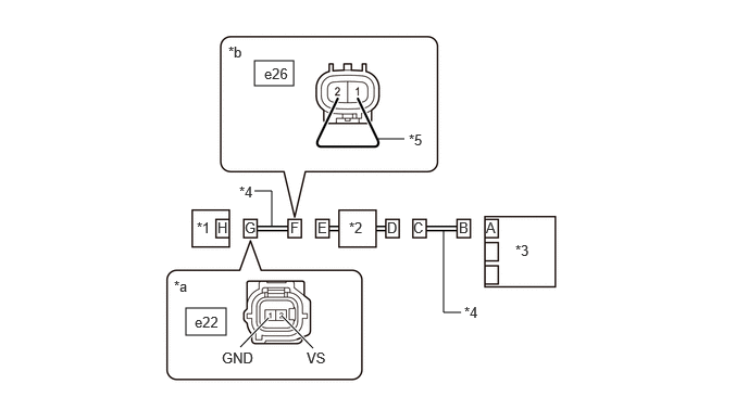
*1 Seat Position Sensor (Separate Type Front Seat Cushion Spring Assembly LH) *2 Front Seat Inner Belt Assembly LH *3 Airbag Sensor Assembly *4 Wire Harness *5 Service Wire - - *a Front view of wire harness connector
(to Seat Position Sensor (Separate Type Front Seat Cushion Spring Assembly LH))*b Front view of wire harness connector
(to Front Seat Inner Belt Assembly LH)Standard Resistance
Tester Connection Condition Specified Condition e22-2 (VS) - e22-1 (GND) Always Below 1 Ω Result
Proceed to OK NG Post-procedure1
- Disconnect the service wire from connector F.
Result:
NG
REPAIR OR REPLACE HARNESS OR CONNECTOR
Result:
OK
See step 20
- Using a service wire, connect terminals 2 and 1 of connector F.
- CHECK HARNESS AND CONNECTOR (FRONT SEAT INNER BELT ASSEMBLY LH - AIRBAG SENSOR ASSEMBLY)
Pre-procedure1
- Using a service wire, connect terminals 27 (LSP+) and 24 (GNDL) of connector B.NOTE:
Do not forcibly insert the service wire into the terminals of the connector when connecting a service wire.
Procedure1
- Measure the resistance according to the value(s) in the table below.
*1 Seat Position Sensor (Separate Type Front Seat Cushion Spring Assembly LH) *2 Front Seat Inner Belt Assembly LH *3 Airbag Sensor Assembly *4 Wire Harness *5 Service Wire - - *a Front view of wire harness connector
(to Front Seat Inner Belt Assembly LH)*b Front view of wire harness connector
(to Airbag Sensor Assembly)Standard Resistance
Tester Connection Condition Specified Condition M70-4 (LSP+) - M70-3 (LSP-) Always Below 1 Ω Result
Proceed to OK NG Post-procedure1
- Disconnect the service wire from connector B.
Result:
OK
REPLACE FRONT SEAT INNER BELT ASSEMBLY LH. Refer to REMOVAL [11/2023 - ]
Result:
NG
REPAIR OR REPLACE HARNESS OR CONNECTOR
- Using a service wire, connect terminals 27 (LSP+) and 24 (GNDL) of connector B.