DTC B0092-87: Left Side Restraints Sensor 2 Missing Message [11/2023 - ]: Procedure
- CHECK CONNECTION OF CONNECTORS
Pre-procedure1
- Turn the ignition switch off.
- Disconnect the cable from the negative (-) auxiliary battery terminal, and wait for at least 60 seconds.
Procedure1
- Check that the connectors are properly connected to the airbag sensor assembly and side No. 2 airbag sensor LH.
OK
The connectors are properly connected.
Result
Proceed to OK NG Post-procedure1
- None
Result:
NG
CONNECT CONNECTORS PROPERLY
Result:
OK
See step 2
- CHECK CONNECTORS
Pre-procedure1
- Disconnect the airbag sensor assembly connector.
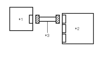
*1 Side No. 2 Airbag Sensor LH *2 Airbag Sensor Assembly *3 Wire Harness - Disconnect the side No. 2 airbag sensor LH connector.
Procedure1
- Check that the terminals of the connectors are not deformed or damaged.
OK
The terminals are not deformed or damaged.
Result
Proceed to OK NG Post-procedure1
- None
Result:
NG
REPAIR OR REPLACE HARNESS OR CONNECTOR
Result:
OK
See step 3
- Disconnect the airbag sensor assembly connector.
- CHECK HARNESS AND CONNECTOR (CHECK FOR SHORT IN THE CIRCUIT)
- Measure the resistance according to the value(s) in the table below.
Standard Resistance
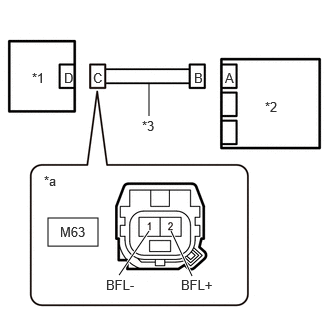
Tester Connection Condition Specified Condition M63-2 (BFL+) - M63-1 (BFL-) Always 1 MΩ or higher *1 Side No. 2 Airbag Sensor LH *2 Airbag Sensor Assembly *3 Wire Harness *a Front view of wire harness connector
(to Side No. 2 Airbag Sensor LH)Result
Proceed to OK NG
Result:
NG
REPAIR OR REPLACE HARNESS OR CONNECTOR
Result:
OK
See step 4
- Measure the resistance according to the value(s) in the table below.
- CHECK HARNESS AND CONNECTOR (CHECK FOR OPEN IN THE CIRCUIT)
Pre-procedure1
- Using a service wire, connect terminals 28 (BCL+) and 29 (BCL-) of connector B.
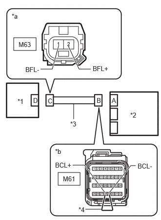
*1 Side No. 2 Airbag Sensor LH *2 Airbag Sensor Assembly *3 Wire Harness *4 Service Wire *a Front view of wire harness connector
(to Side No. 2 Airbag Sensor LH)*b Front view of wire harness connector
(to Airbag Sensor Assembly)NOTE:Do not forcibly insert the service wire into the terminals of the connector when connecting a service wire.
Procedure1
- Measure the resistance according to the value(s) in the table below.
Standard Resistance
Tester Connection Condition Specified Condition M63-2 (BFL+) - M63-1 (BFL-) Always Below 1 Ω Result
Proceed to OK NG Post-procedure1
- Disconnect the service wire from connector B.
Result:
NG
REPAIR OR REPLACE HARNESS OR CONNECTOR
Result:
OK
See step 5
- Using a service wire, connect terminals 28 (BCL+) and 29 (BCL-) of connector B.
- CHECK HARNESS AND CONNECTOR (CHECK FOR SHORT TO GROUND IN THE CIRCUIT)
- Measure the resistance according to the value(s) in the table below.
Standard Resistance
Tester Connection Condition Specified Condition M63-2 (BFL+) - Body ground Always 1 MΩ or higher M63-1 (BFL-) - Body ground Always 1 MΩ or higher *1 Side No. 2 Airbag Sensor LH *2 Airbag Sensor Assembly *3 Wire Harness *a Front view of wire harness connector
(to Side No. 2 Airbag Sensor LH)Result
Proceed to OK NG
Result:
NG
REPAIR OR REPLACE HARNESS OR CONNECTOR
Result:
OK
See step 6
- Measure the resistance according to the value(s) in the table below.
- CHECK HARNESS AND CONNECTOR (CHECK FOR SHORT TO +B IN THE CIRCUIT)
Pre-procedure1
- Connect the cable to the negative (-) auxiliary battery terminal, and wait for at least 2 seconds.
- Turn the ignition switch to ON.
Procedure1
- Measure the voltage according to the value(s) in the table below.
*1 Side No. 2 Airbag Sensor LH *2 Airbag Sensor Assembly *3 Wire Harness *a Front view of wire harness connector
(to Side No. 2 Airbag Sensor LH)Standard Voltage
Tester Connection Condition Specified Condition M63-2 (BFL+) - Body ground Ignition switch ON Below 1 V M63-1 (BFL-) - Body ground Ignition switch ON Below 1 V Result
Proceed to OK NG Post-procedure1
- Turn the ignition switch off.
- Disconnect the cable from the negative (-) auxiliary battery terminal, and wait for at least 60 seconds.
Result:
NG
REPAIR OR REPLACE HARNESS OR CONNECTOR
Result:
OK
See step 7
- CLEAR DTC
Pre-procedure1
- Connect the airbag sensor assembly connector.
*1 Side No. 2 Airbag Sensor RH *2 Airbag Sensor Assembly *3 Wire Harness - Interchange the side No. 2 airbag sensor LH with RH and connect the connectors to them.
- Connect the cable to the negative (-) auxiliary battery terminal, and wait for at least 2 seconds.
- Turn the ignition switch to ON, and wait for at least 60 seconds.
Procedure1
- Clear the DTCs stored in memory.
Body Electrical > SRS Airbag > Clear DTCs
Result
Proceed to NEXT Post-procedure1
- Turn the ignition switch off.
Result:
NEXT
See step 8
- Connect the airbag sensor assembly connector.
- CHECK SIDE NO. 2 AIRBAG SENSOR LH
Pre-procedure1
- Turn the ignition switch to ON, and wait for at least 60 seconds.
Procedure1
- Check for DTCs.
Body Electrical > SRS Airbag > Trouble Codes
Result
Result Proceed to B0092-87 is output A B0097-87 is output B B0092-87 and B0097-87 are not output C HINT:
Codes other than DTCs B0092-87 and B0097-87 may be output at this time, but they are not related to this check.
Post-procedure1
- Turn the ignition switch off.
- Disconnect the cable from the negative (-) auxiliary battery terminal, and wait for at least 60 seconds.
- Return the side No. 2 airbag sensor RH and LH to their original positions and connect the connectors to them.
Result:
A
REPLACE AIRBAG SENSOR ASSEMBLY. Refer to REMOVAL [11/2023 - ]
Result:
B
REPLACE SIDE NO. 2 AIRBAG SENSOR LH. Refer to REMOVAL [11/2023 - ]
Result:
C
USE SIMULATION METHOD TO CHECK. Refer to HOW TO PROCEED WITH TROUBLESHOOTING [12/2019 - ]
- Turn the ignition switch to ON, and wait for at least 60 seconds.