DTC B0002-13: Driver Frontal Stage 2 Deployment Control Circuit Open [11/2023 - ]: Procedure
- CLEAR DTC
Pre-procedure1
- Turn the ignition switch to ON, and wait for at least 60 seconds.
Procedure1
- Clear the DTCs stored in memory.
Body Electrical > SRS Airbag > Clear DTCs
Result
Proceed to NEXT Post-procedure1
- Turn the ignition switch off.
Result:
NEXT
See step 2
- Turn the ignition switch to ON, and wait for at least 60 seconds.
- CHECK DTC
Pre-procedure1
- Turn the ignition switch to ON, and wait for at least 60 seconds.
Procedure1
- Check for DTCs.
Body Electrical > SRS Airbag > Trouble Codes
Result
Result Proceed to B0002-13 is output A B0002-13 is not output B Post-procedure1
- None
Result:
B
USE SIMULATION METHOD TO CHECK. Refer to HOW TO PROCEED WITH TROUBLESHOOTING [12/2019 - ]
Result:
A
See step 3
- Turn the ignition switch to ON, and wait for at least 60 seconds.
- CHECK CONNECTION OF CONNECTORS
Pre-procedure1
- Turn the ignition switch off.
- Disconnect the cable from the negative (-) auxiliary battery terminal, and wait for at least 60 seconds.
Procedure1
- Check that the connectors are properly connected to the horn button assembly, spiral cable sub-assembly and airbag sensor assembly.
OK
The connectors are properly connected.
Result
Proceed to OK NG Post-procedure1
- None
Result:
NG
CONNECT CONNECTORS PROPERLY
Result:
OK
See step 4
- CHECK CONNECTORS
Pre-procedure1
- Disconnect the airbag sensor assembly connector.
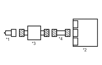
*1 Horn Button Assembly *2 Airbag Sensor Assembly *3 Spiral Cable Sub-assembly *4 Wire Harness - Disconnect the spiral cable sub-assembly connector.
- Disconnect the horn button assembly connector.
Procedure1
- Check that the terminals of the connectors are not deformed or damaged.
OK
The terminals are not deformed or damaged.
- Check that the connectors are not loose, deformed or damaged.
OK
The connector locking button is not disengaged, and the claw of the lock is not deformed or damaged.
- Check that the short springs of the activation prevention mechanisms of the wire harness connector and spiral cable sub-assembly connector are not deformed or damaged.
OK
The short springs are not deformed or damaged.
Result
Proceed to OK NG Post-procedure1
- None
Result:
NG
REPAIR OR REPLACE WIRE HARNESS OR SPIRAL CABLE SUB-ASSEMBLY
Result:
OK
See step 5
- Disconnect the airbag sensor assembly connector.
- CLEAR DTC
Pre-procedure1
- Connect the airbag sensor assembly connector.
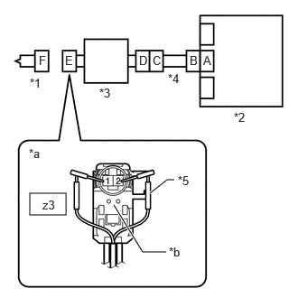
*1 Horn Button Assembly *2 Airbag Sensor Assembly *3 Spiral Cable Sub-assembly *4 Wire Harness *5 SST *a Front view of wire harness connector
(to Horn Button Assembly)*b Color: Black - Connect the spiral cable sub-assembly connector.
- Connect SST (resistance: 2.1 Ω) to connector E (black connector).WARNING:
Never connect the tester to the horn button assembly for measurement, as this may lead to a serious injury due to airbag deployment.
NOTE:- Do not forcibly insert SST into the terminals of the connector when connecting SST.
- Insert SST straight into the terminals of the connector.
- SST: 09843-18061
- Connect the cable to the negative (-) auxiliary battery terminal, and wait for at least 2 seconds.
- Turn the ignition switch to ON, and wait for at least 60 seconds.
Procedure1
- Clear the DTCs stored in memory.
Body Electrical > SRS Airbag > Clear DTCs
Result
Proceed to NEXT Post-procedure1
- Turn the ignition switch off.
Result:
NEXT
See step 6
- Connect the airbag sensor assembly connector.
- CHECK HORN BUTTON ASSEMBLY
Pre-procedure1
- Turn the ignition switch to ON, and wait for at least 60 seconds.
Procedure1
- Check for DTCs.
Body Electrical > SRS Airbag > Trouble Codes
Result
Result Proceed to B0002-13 is not output A B0002-13 is output B HINT:
Codes other than DTC B0002-13 may be output at this time, but they are not related to this check.
Post-procedure1
- Turn the ignition switch off.
- Disconnect the cable from the negative (-) auxiliary battery terminal, and wait for at least 60 seconds.
- Disconnect SST from connector E.
Result:
A
REPLACE HORN BUTTON ASSEMBLY. Refer to REMOVAL [11/2023 - ]
Result:
B
See step 7
- Turn the ignition switch to ON, and wait for at least 60 seconds.
- CHECK DRIVER SIDE 2ND SQUIB CIRCUIT
Pre-procedure1
- Disconnect the airbag sensor assembly connector.
Procedure1
- Measure the resistance according to the value(s) in the table below.
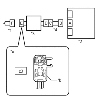
*1 Horn Button Assembly *2 Airbag Sensor Assembly *3 Spiral Cable Sub-assembly *4 Wire Harness *a Front view of wire harness connector
(to Horn Button Assembly)*b Color: Black Standard Resistance
Tester Connection Condition Specified Condition z3-1 - z3-2 Always Below 1 Ω Result
Proceed to OK NG Post-procedure1
- None
Result:
NG
See step 10
Result:
OK
See step 8
- Disconnect the airbag sensor assembly connector.
- CLEAR DTC
Pre-procedure1
- Connect the airbag sensor assembly connector.
*1 Horn Button Assembly *2 Airbag Sensor Assembly *3 Spiral Cable Sub-assembly *4 Wire Harness - Connect the horn button assembly connector.
- Connect the cable to the negative (-) auxiliary battery terminal, and wait for at least 2 seconds.
- Turn the ignition switch to ON, and wait for at least 60 seconds.
Procedure1
- Clear the DTCs stored in memory.
Body Electrical > SRS Airbag > Clear DTCs
Result
Proceed to NEXT Post-procedure1
- Turn the ignition switch off.
Result:
NEXT
See step 9
- Connect the airbag sensor assembly connector.
- CHECK DTC
Pre-procedure1
- Turn the ignition switch to ON, and wait for at least 60 seconds.
Procedure1
- Check for DTCs.
Body Electrical > SRS Airbag > Trouble Codes
Result
Result Proceed to B0002-13 is not output A B0002-13 is output B HINT:
Codes other than DTC B0002-13 may be output at this time, but they are not related to this check.
Post-procedure1
- None
Result:
A
USE SIMULATION METHOD TO CHECK. Refer to HOW TO PROCEED WITH TROUBLESHOOTING [12/2019 - ]
Result:
B
REPLACE AIRBAG SENSOR ASSEMBLY. Refer to REMOVAL [11/2023 - ]
- Turn the ignition switch to ON, and wait for at least 60 seconds.
- CHECK HARNESS AND CONNECTOR
Pre-procedure1
- Disconnect the spiral cable sub-assembly connector.
Procedure1
- Measure the resistance according to the value(s) in the table below.
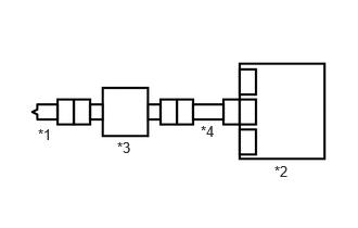
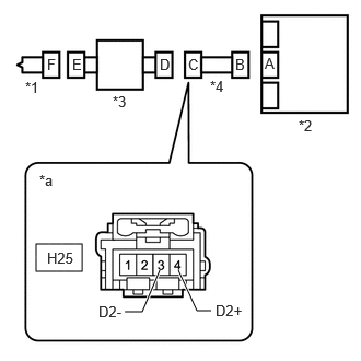
*1 Horn Button Assembly *2 Airbag Sensor Assembly *3 Spiral Cable Sub-assembly *4 Wire Harness *a Front view of wire harness connector
(to Spiral Cable Sub-assembly)Standard Resistance
Tester Connection Condition Specified Condition H25-3 (D2-) - H25-4 (D2+) Always Below 1 Ω Result
Proceed to OK NG Post-procedure1
- None
Result:
OK
REPLACE SPIRAL CABLE SUB-ASSEMBLY. Refer to REMOVAL [11/2023 - ]
Result:
NG
REPAIR OR REPLACE HARNESS OR CONNECTOR
- Disconnect the spiral cable sub-assembly connector.