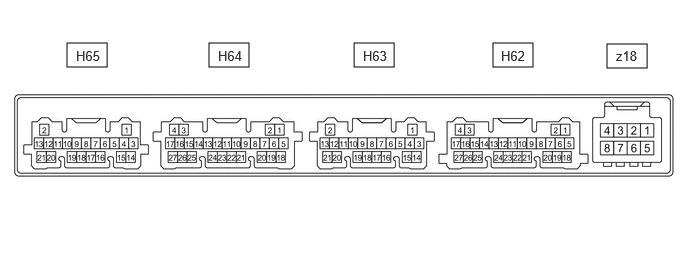
Terminals Of Ecu [12/2019 - 10/2022]
- CHECK AIR CONDITIONING AMPLIFIER ASSEMBLY
HINT:
Make sure to wait at least 2 minutes after turning the ignition switch off before performing an ECU terminal inspection.
CHANNEL 1 (Z18)Terminal No.
(Symbol)Terminal Description Condition Specified Condition z18-2 (BUS G) - Body ground Ground for BUS IC Always Below 1 V z18-3 (BUS) - z18-2 (BUS G) BUS IC control signal Ignition switch ON Pulse generation
(See waveform "Servo LIN communication")z18-4 (B BUS) - z18-2 (BUS G) Power supply for BUS IC Ignition switch off 11 to 14 V z18-5 (SG) - Body ground Ground for evaporator temp. sensor (No. 1 cooler thermistor) Always Below 1 V z18-6 (TE) - z18-5 (SG) Evaporator temp. sensor (No. 1 cooler thermistor) signal - Ignition switch ON
- Evaporator temperature: 0°C (32°F)
1.7 to 2.1 V - Ignition switch ON
- Evaporator temperature: 15°C (59°F)
0.9 to 1.3 V CHANNEL 2 (H62)Terminal No.
(Symbol)Terminal Description Condition Specified Condition H62-2 (CANH) - H62-1 (CANL) CAN communication system CAN communication is performed Pulse generation H62-5 (B) - H62-17 (GND) Power source (Back-up) Ignition switch off 11 to 14 V H62-6 (IG+) - H62-17 (GND) Power source (IG) Ignition switch ON 11 to 14 V Ignition switch off Below 1 V H62-7 (LIN1) - H62-17 (GND) LIN communication signal Ignition switch ON Pulse generation
(See waveform "Control panel LIN communication")H62-17 (GND) - Body ground Ground for main power supply Always Below 1 V H62-18 (SOL+) - H62-17 (GND) Compressor solenoid operation signal - Engine running
- Blower switch: LO
- A/C switch: On
Pulse generation
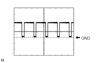
(See waveform "Compressor solenoid")H62-21 (BLW) - H62-17 (GND) Blower motor speed control signal - Ignition switch ON
- Blower switch: LO
Pulse generation
(See waveform "Blower")H62-23 (PTC1)* - H62-17 (GND) Quick heater assembly operation signal - Ignition switch ON
- Temperature setting: MAX HOT
- Ambient temperature: 10°C (50°F) or lower
- Engine coolant temperature: 65°C (149°F) or lower
- Light control switch off
- Blower switch: On
Below 1 V - Ignition switch ON
- Temperature setting: MAX HOT
- Ambient temperature: 10°C (50°F) or lower
- Engine coolant temperature: 65°C (149°F) or lower
- Light control switch off
- Blower switch: Off
11 to 14 V *: w/ Quick Heater
CHANNEL 3 (H63)Terminal No.
(Symbol)Terminal Description Condition Specified Condition H63-1 (TAM) - H63-14 (SG-2) Ambient temp. sensor (thermistor assembly) signal - Ignition switch ON
- Ambient temperature: 25°C (77°F)
1.05 to 1.45 V - Ignition switch ON
- Ambient temperature: 40°C (104°F)
0.64 to 0.87 V H63-3 (SG-1) - Body ground Ground for room temp. sensor (cooler thermistor) Always Below 1 V H63-5 (TR) - H63-3 (SG-1) Room temp. sensor (cooler thermistor) signal - Ignition switch ON
- Cabin temperature: 25°C (77°F)
1.05 to 1.45 V - Ignition switch ON
- Cabin temperature: 40°C (104°F)
0.64 to 0.87 V H63-6 (PRE) - H63-15 (SG-4) Air conditioner pressure sensor signal - Engine start
- Air conditioning system operating
- Refrigerant pressure: Abnormal pressure (more than 2812 kPaG (28.7 kgf/cm2 , 408 psi))
4.61 V or higher - Engine start
- Air conditioning system operating
- Refrigerant pressure: Abnormal pressure (less than 196 kPaG (2.0 kgf/cm2 , 28 psi))
Below 0.74 V - Engine start
- Air conditioning system operating
- Refrigerant pressure: Normal pressure (less than 2812 kPaG (28.7 kgf/cm2 , 408 psi) and more than 196 kPaG (2.0 kgf/cm2 , 28 psi))
0.74 to 4.61 V H63-11 (S5-3) - H63-15 (SG-4) Power supply for air conditioner pressure sensor Ignition switch ON 4.75 to 5.25 V Ignition switch off Below 1 V H63-12 (LOCK) - H63-14 (SG-2) A/C lock sensor signal - Engine running
- Blower switch: LO
- A/C switch: On
Pulse generation
(See waveform "A/C lock sensor")H63-14 (SG-2) - Body ground Ground for ambient temp. sensor (thermistor assembly) Always Below 1 V H63-15 (SG-4) - Body ground Ground for air conditioner pressure sensor Always Below 1 V H63-16 (PTC2)* - H62-17 (GND) Quick heater assembly operation signal - Ignition switch ON
- Temperature setting: MAX HOT
- Ambient temperature: 0°C (32°F) or lower
- Engine coolant temperature: 62.5°C (144.5°F) or lower
- Light control switch off
- Blower switch: On
Below 1 V - Ignition switch ON
- Temperature setting: MAX HOT
- Ambient temperature: 0°C (32°F) or lower
- Engine coolant temperature: 62.5°C (144.5°F) or lower
- Light control switch off
- Blower switch: Off
11 to 14 V H63-19 (MGC) - H62-17 (GND) Magnetic clutch operation signal - Engine running
- Blower switch: LO
- A/C switch: Off
11 to 14 V - Engine running
- Blower switch: LO
- A/C switch: On
Below 1 V *: w/ Quick Heater
CHANNEL 4 (H64)Terminal No.
(Symbol)Terminal Description Condition Specified Condition H64-1 (+B2) - H62-17 (GND) Power source (Back-up) Ignition switch off 11 to 14 V H64-2 (RBBU) - H64-3 (RBUG) Power supply for BUS IC Ignition switch off 11 to 14 V H64-3 (RBUG) - Body ground Ground for BUS IC Always Below 1 V H64-4 (GND2) - Body ground Ground for main power supply Always Below 1 V H64-7 (RBUS) - H64-3 (RBUG) BUS IC control signal Ignition switch ON Pulse generation
(See waveform "Servo LIN communication")H64-10 (SBLW) - H62-17 (GND) Blower motor speed control signal - Ignition switch ON
- Blower switch: LO
Pulse generation
(See waveform "Blower")H64-20 (RLIN) - H62-17 (GND) LIN communication signal Ignition switch ON Pulse generation
(See waveform "Control panel LIN communication")CHANNEL 5 (H65)Terminal No.
(Symbol)Terminal Description Condition Specified Condition H65-8 (TR) - H65-14 (SG-8) No. 2 room temp. sensor (cooler thermistor) signal - Ignition switch ON
- Cabin temperature: 25°C (77°F)
1.05 to 1.45 V - Ignition switch ON
- Cabin temperature: 40°C (104°F)
0.64 to 0.87 V H65-11 (TEC) - H65-15 (SG-9) Rear evaporator temp. sensor (No. 2 air conditioning harness assembly) signal - Ignition switch ON
- Evaporator temperature: 0°C (32°F)
1.7 to 2.1 V - Ignition switch ON
- Evaporator temperature: 15°C (59°F)
0.9 to 1.3 V H65-14 (SG-8) - Body ground Ground for No. 2 room temp. sensor (cooler thermistor) Always Below 1 V H65-15 (SG-9) - Body ground Ground for Rear evaporator temp. sensor (No. 2 air conditioning harness assembly) Always Below 1 V - Waveform "Blower":
Item Content Terminal No. - H62-21 (BLW) - H62-17 (GND)
- H64-10 (SBLW) - H62-17 (GND)
Tool Setting 2 V/DIV., 1 ms./DIV. Condition - Ignition switch ON
- Blower switch: LO
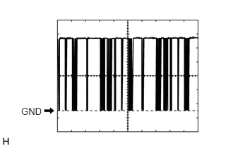
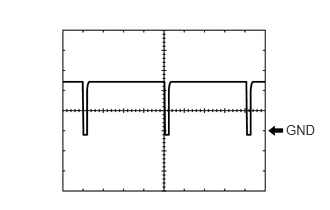
- Waveform "Control panel LIN communication":
Item Content Terminal No. - H62-7 (LIN1) - H62-17 (GND)
- H64-20 (RLIN) - H62-17 (GND)
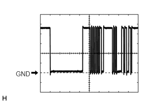
Tool Setting 2 V/DIV., 20 ms./DIV. Condition Ignition switch ON - Waveform "Servo LIN communication":
Item Content Terminal No. - z18-3 (BUS) - z18-2 (BUS G)
- H64-7 (RBUS) - H64-3 (RBUG)
Tool Setting 2 V/DIV., 2 ms./DIV. Condition Ignition switch ON - Waveform "A/C lock sensor":
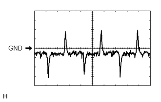
Item Content Terminal No. H63-12 (LOCK) - H63-14 (SG-2) Tool Setting 200 mV/DIV., 10 ms./DIV. Condition - Engine running
- Blower switch: LO
- A/C switch: On
- Waveform "Compressor solenoid":
Item Content Terminal No. H62-18 (SOL+) - H62-17 (GND) Tool Setting 5 V/DIV., 500 μs./DIV. Condition - Engine running
- Blower switch: LO
- A/C switch: On
- CHECK AIR CONDITIONING CONTROL ASSEMBLY (w/o Toyota Multi Operation Touch System)
HINT:
Check from the rear of the connector while it is connected to the air conditioning control assembly.
Terminal No.
(Symbol)Terminal Description Condition Specified Condition H27-1 (ILL+) - Body ground Illumination signal Taillight off Below 1 V Taillight on 11 to 14 V H27-5 (ILL-) - Body ground Illumination signal Always Below 1 V H27-6 (IG+) - H27-10 (GND) Power source (IG) Ignition switch off Below 1 V Ignition switch ON 11 to 14 V H27-8 (LIN1) - Body ground LIN communication signal Ignition switch ON Pulse generation
(See waveform)H27-10 (GND) - Body ground Ground for air conditioning control assembly Always Below 1 V - CHECK AIR CONDITIONING CONTROL ASSEMBLY (w/ Toyota Multi Operation Touch System)
HINT:
Check from the rear of the connector while it is connected to the air conditioning control assembly.
Terminal No.
(Symbol)Terminal Description Condition Specified Condition H27-3 (LIN1) - Body ground LIN communication signal Ignition switch ON Pulse generation
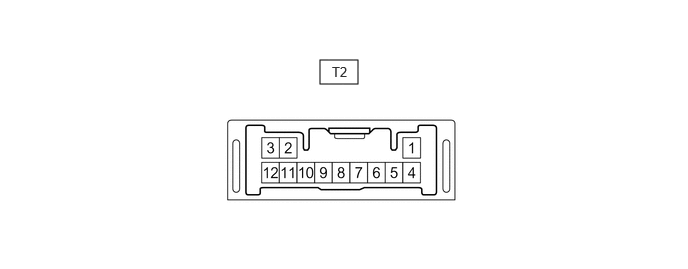
(See waveform)H27-4 (IG+) - H27-8 (E) Power source (IG) Ignition switch off Below 1 V Ignition switch ON 11 to 14 V H27-5 (ILL+) - Body ground Illumination signal Taillight off Below 1 V Taillight on 11 to 14 V H27-8 (E) - Body ground Ground for air conditioning control assembly Always Below 1 V H27-10 (ILL-) - Body ground Illumination signal Always Below 1 V - CHECK NO. 2 AIR CONDITIONING CONTROL ASSEMBLY
HINT:
Check from the rear of the connector while it is connected to the No. 2 air conditioning control assembly.
Terminal No.
(Symbol)Terminal Description Condition Specified Condition T2-6 (ILL-) - Body ground Illumination signal Always Below 1 V T2-7 (E) - Body ground Ground for No. 2 air conditioning control assembly Always Below 1 V T2-8 (RLIN) - Body ground LIN communication signal Ignition switch ON Pulse generation
(See waveform)T2-9 (IG) - T2-7 (E) Power source (IG) Ignition switch off Below 1 V Ignition switch ON 11 to 14 V T2-10 (ILL+) - Body ground Illumination signal Taillight off Below 1 V Taillight on 11 to 14 V