Terminals Of Ecu [12/2019 - ]
- CHECK SKID CONTROL ECU (BRAKE ACTUATOR ASSEMBLY)
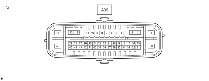
*a Component without harness connected
(Skid Control ECU (Brake Actuator Assembly))- - - Disconnect the A39 skid control ECU (brake actuator assembly) connectors.
- Measure the voltage and resistance according to the value (s) in the table below.
Terminal No. (Symbol) Terminal Description Condition Specified Condition A39-14 (+BS) - Body ground Parking brake motor (parking brake actuator assembly) power supply Always 11 to 14 V A39-45 (IG1) - Body ground IG power supply Ignition switch ON 11 to 14 V*1
10.5 to 16 V*2A39-1 (GND1) - Body ground Ground Always Below 1 Ω A39-13 (MRR+) Parking brake motor RH (parking brake actuator assembly RH) (+) - - A39-12 (MRR-) Parking brake motor RH (parking brake actuator assembly RH) (-) - - A39-3 (MRL+) Parking brake motor LH (parking brake actuator assembly LH) (+) - - A39-2 (MRL-) Parking brake motor LH (parking brake actuator assembly LH) (-) - - A39-38 (POL) Electric parking brake switch indicator light - - A39-36 (SWI1) Electric parking brake switch (electric parking brake switch assembly) - - A39-31 (SWO1) Electric parking brake switch (electric parking brake switch assembly) - - A39-41 (SWI2) Electric parking brake switch (electric parking brake switch assembly) - - A39-39 (SWO2) Electric parking brake switch (electric parking brake switch assembly) - - A39-27 (CANH) CAN communication line H - - A39-43 (CANL) CAN communication line L - - *1: w/o Stop and Start System
*2: w/ Stop and Start System