DTC C0613-2A: Right Electric Parking Brake Actuator Signal Stuck In Range [12/2019 - ]: Procedure
- CHECK DTC
- Using the GTS, check for DTCs other than DTC C0613-2A.
Chassis > Brake/EPB > Trouble Codes
Result
Result Proceed to Only DTC C0613-2A is output A DTCs other than C0613-2A are output B
Result:
B
GO TO DIAGNOSTIC TROUBLE CODE CHART. Refer to DIAGNOSTIC TROUBLE CODE CHART [12/2019 - 11/2023] , or refer to DIAGNOSTIC TROUBLE CODE CHART [11/2023 - ]
Result:
A
See step 2
- Using the GTS, check for DTCs other than DTC C0613-2A.
- INSPECT NO. 1 PARKING BRAKE WIRE ASSEMBLY
- Turn the ignition switch off.
- Make sure that there is no looseness at the locking part and the connecting part of the connectors.
OK
The connector is securely connected.
- Disconnect the uM1 and u1 No. 1 parking brake wire assembly connectors.
- Check both the connector case and the terminals for deformation and corrosion.
OK
No deformation or corrosion.
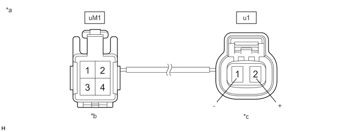
- Measure the resistance according to the value(s) in the table below.
*a Front view of No. 1 Parking Brake Wire Assembly *b (to wire harness connector) *c (to Parking Brake Actuator Assembly RH) - - Standard Resistance
Tester Connection Condition Specified Condition uM1-1 - u1-2 (+) Always Below 1 Ω uM1-1 or u1-2 (+) - Body ground and other terminals Always 10 kΩ or higher uM1-2 - u1-1 (-) Always Below 1 Ω uM1-2 or u1-1 (-) - Body ground and other terminals Always 10 kΩ or higher Result
Proceed to OK NG
Result:
NG
REPLACE NO. 1 PARKING BRAKE WIRE ASSEMBLY
Result:
OK
See step 3
- CHECK HARNESS AND CONNECTOR (SKID CONTROL ECU (BRAKE ACTUATOR ASSEMBLY) - PARKING BRAKE ACTUATOR ASSEMBLY RH)
- Turn the ignition switch off.
- Make sure the No. 1 parking brake wire assembly is securely installed.
- Disconnect the A39 skid control ECU (brake actuator assembly) connector.
- Disconnect the u1 parking brake actuator assembly RH connector.
- Measure the resistance according to the value(s) in the table below.
Standard Resistance
Tester Connection Condition Specified Condition A39-13 (MRR+) - u1-2 (+) Always Below 1 Ω A39-12 (MRR-) - u1-1 (-) Always Below 1 Ω A39-13 (MRR+) or u1-2 (+) - Body ground Always 10 kΩ or higher A39-12 (MRR-) or u1-1 (-) - Body ground Always 10 kΩ or higher Result
Proceed to OK NG
Result:
NG
REPAIR OR REPLACE HARNESS OR CONNECTOR
Result:
OK
See step 4
- INSPECT REAR BRAKE AND PARKING BRAKE ACTUATOR ASSEMBLY RH (CHECK FOR ROTATING PARTS THAT ARE STUCK AND FOR FREE SPINNING ACTUATORS)
- Enter rear brake pad replacement mode.
Refer to TEST MODE PROCEDURE [12/2019 - ]
- Turn the ignition switch off.
- Check that the rotating parts are not seized or the actuator is not spinning freely.
- Check that the parking brake actuator assembly RH is installed properly to the rear brake caliper and that it is not spinning freely.
For the parking brake actuator assembly RH removal procedure: Refer to REMOVAL [12/2019 - ]
- Check that there is no damage to the rotating parts from the parking brake actuator assembly RH to the rear brake caliper.
- Inspect the parking brake actuator assembly RH and check that it operates correctly.
Refer to INSPECTION [12/2019 - ]
- Check that the rear brake caliper threaded part rotates and that the rear disc brake piston moves outward.
HINT:
For the check procedures, refer to the parking brake forced release method when not using the GTS.
Refer to OPERATION METHOD [12/2019 - ]
HINT:
Return to normal mode after work is complete.
Refer to TEST MODE PROCEDURE [12/2019 - ]
Result
Result Proceed to Parking brake actuator assembly RH is malfunctioning A Other than parking brake actuator assembly RH is malfunctioning B - Check that the parking brake actuator assembly RH is installed properly to the rear brake caliper and that it is not spinning freely.
Result:
A
REPLACE PARKING BRAKE ACTUATOR ASSEMBLY RH. Refer to REMOVAL [12/2019 - ]
Result:
B
REPAIR OR REPLACE ABNORMAL PARTS
- Enter rear brake pad replacement mode.