DTC C123A-14: Supply Voltage Circuit IG Open [12/2019 - 11/2023]: Procedure
- CHECK HARNESS AND CONNECTOR (IG1 TERMINAL VOLTAGE)
- Disconnect the A39 skid control ECU (brake actuator assembly) connector.
- Turn the ignition switch to ON.
- Measure the voltage according to the value(s) in the table below.
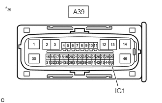
*a Front view of wire harness connector
(to Skid Control ECU (Brake Actuator Assembly))Standard Voltage
Tester Connection Condition Specified Condition A39-45 (IG1) - Body ground Ignition switch ON 11 to 14 V*1
10.5 to 16 V*2*1: w/o Stop and Start System
*2: w/ Stop and Start System
Result
Result Proceed to OK A NG (w/o Stop and Start System) B NG (w/ Stop and Start System) C
Result:
A
REPLACE SKID CONTROL ECU (BRAKE ACTUATOR ASSEMBLY). Refer to REMOVAL [12/2019 - 10/2022] , or refer to REMOVAL [10/2022 - 11/2023]
Result:
B
REPAIR OR REPLACE HARNESS OR CONNECTOR
Result:
C
INSPECT STOP AND START SYSTEM (BACKUP BOOST CONVERTER CIRCUIT). Refer to Backup Boost Converter Circuit [12/2019 - 10/2022] , or refer to Backup Boost Converter Circuit [10/2022 - 11/2023]