Electric Parking Brake does not Operate [12/2019 - 10/2022]: Procedure
- CHECK CAN COMMUNICATION SYSTEM
- Check if CAN communication system DTCs are output.
Chassis > Brake/EPB > Trouble Codes
Result
Result Proceed to DTCs are not output A DTCs are output B
Result:
B
GO TO CAN COMMUNICATION SYSTEM. Refer to HOW TO PROCEED WITH TROUBLESHOOTING [12/2019 - 10/2022]
Result:
A
See step 2
- Check if CAN communication system DTCs are output.
- VEHICLE OPERATION CHECK
- With the wheels not contacting the ground, check the condition of the rear wheels when the electric parking brake is operating and not operating.
Refer to ON-VEHICLE INSPECTION [12/2019 - ]
Result
Result Proceed to Lock and release operation is normal and parking brake indicator light turns off or blinks (red) A Lock and release operation is malfunctioning and parking brake indicator light illuminates (red) or turns off according to switch operation B Lock and release operation is malfunctioning and parking brake indicator light turns off or blinks (red) C
Result:
B
INSPECT REAR BRAKE
Result:
C
See step 4
Result:
A
See step 3
- With the wheels not contacting the ground, check the condition of the rear wheels when the electric parking brake is operating and not operating.
- INSPECT COMBINATION METER ASSEMBLY
- Perform the Active Test of the combination meter assembly using the GTS.
Body Electrical > Combination Meter > Active Test
Tester Display Indicat. Park - Check the combination meter assembly.
OK
Parking brake indicator light (red) turns on or off in accordance with GTS operation.
Result
Proceed to OK NG
Result:
OK
REPLACE SKID CONTROL ECU (BRAKE ACTUATOR ASSEMBLY). Refer to REMOVAL [12/2019 - 10/2022]
Result:
NG
GO TO METER / GAUGE SYSTEM. Refer to HOW TO PROCEED WITH TROUBLESHOOTING [12/2019 - ]
- Perform the Active Test of the combination meter assembly using the GTS.
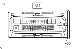
- CHECK HARNESS AND CONNECTOR (+BS TERMINAL VOLTAGE)
- Turn the ignition switch off.
- Disconnect the A39 skid control ECU (brake actuator assembly) connector.
- Measure the voltage according to the value(s) in the table below.
*a Front view of wire harness connector
(to Skid Control ECU (Brake Actuator Assembly))Standard Voltage
Tester Connection Condition Specified Condition A39-14 (+BS) - Body ground Always 11 to 14 V Result
Proceed to OK NG
Result:
NG
REPAIR OR REPLACE HARNESS OR CONNECTOR
Result:
OK
See step 5
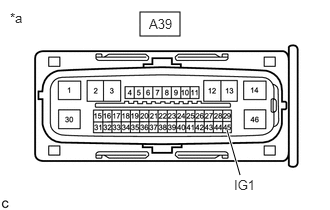
- CHECK HARNESS AND CONNECTOR (IG1 TERMINAL VOLTAGE)
- Turn the ignition switch off.
- Disconnect the A39 skid control ECU (brake actuator assembly) connector.
- Measure the voltage according to the value(s) in the table below.
*a Front view of wire harness connector
(to Skid Control ECU (Brake Actuator Assembly))Standard Voltage
Tester Connection Condition Specified Condition A39-45 (IG1) - Body ground Ignition switch ON 11 to 14 V*1
10.5 to 16 V*2*1: w/o Stop and Start System
*2: w/ Stop and Start System
Result
Result Proceed to OK A NG (w/o Stop and Start System) B NG (w/ Stop and Start System) C
Result:
A
REPLACE SKID CONTROL ECU (BRAKE ACTUATOR ASSEMBLY). Refer to REMOVAL [12/2019 - 10/2022]
Result:
B
REPAIR OR REPLACE HARNESS OR CONNECTOR
Result:
C
INSPECT STOP AND START SYSTEM (BACKUP BOOST CONVERTER CIRCUIT). Refer to Backup Boost Converter Circuit [12/2019 - 10/2022]