DTC C13ED-1C: 4WD/AWD Ring Gear Revolution Sensor Circuit Voltage Out of Range [12/2019 - ]: Procedure
- INSPECT TRANSMISSION REVOLUTION SENSOR
- Remove the transmission revolution sensor.
Refer to DISASSEMBLY [12/2019 - ]
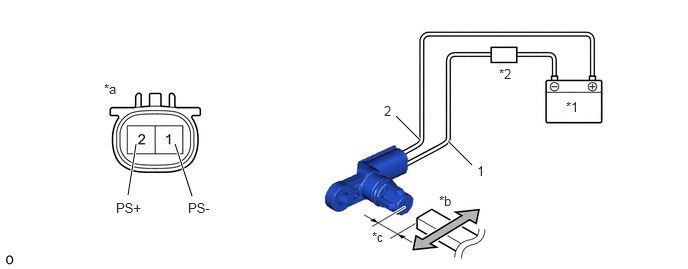
- Connect the battery to the transmission revolution sensor as shown in the illustration.
*1 Battery *2 Ammeter *a Component without harness connected
(Transmission Revolution Sensor)*b Magnet *c 5 mm (0.197 in.) - - - Wave a magnet left and right 5 mm (0.197 in.) or less from the tip of the transmission revolution sensor to output a high/low signal while measuring the current.NOTE:
Make sure to wave the magnet during the inspection. The current will not change unless the magnet is moved as shown in the illustration.
- Measure the current according to the value(s) in the table below.
Standard Current
Tester Connection Condition Specified Condition 1 (PS-) - 2 (PS+) Low signal (Move magnet closer) 6 mA 1 (PS-) - 2 (PS+) High signal (Move magnet away) 14 mA Result
Proceed to OK NG
Result:
NG
REPLACE TRANSMISSION REVOLUTION SENSOR. Refer to DISASSEMBLY [12/2019 - ]
Result:
OK
See step 2
- Remove the transmission revolution sensor.
- CHECK HARNESS AND CONNECTOR (4WD ECU ASSEMBLY - TRANSMISSION REVOLUTION SENSOR)
- Disconnect the s5 transmission revolution sensor connector.
- Disconnect the M41 4WD ECU assembly connector.
- Measure the resistance according to the value(s) in the table below.
Standard Resistance
Tester Connection Condition Specified Condition s5-2 (PS+) - M41-19 (PS+) Always Below 1 Ω s5-1 (PS-) - M41-9 (PS-) Always Below 1 Ω s5-2 (PS+) or M41-19 (PS+) - Body ground and other terminals Always 10 kΩ or higher s5-1 (PS-) or M41-9 (PS-) - Body ground and other terminals Always 10 kΩ or higher Result
Proceed to OK NG
Result:
OK
REPLACE 4WD ECU ASSEMBLY. Refer to REMOVAL [12/2019 - ]
Result:
NG
REPAIR OR REPLACE HARNESS OR CONNECTOR