DTC P0705-13: Transmission Range Sensor "A" Circuit Open; DTC P0705-62: Transmission Range Sensor "A" Signal Compare Failure [12/2019 - 10/2022]: Procedure
- CHECK HARNESS AND CONNECTOR (BATTERY - PARK/NEUTRAL POSITION SWITCH ASSEMBLY)
- Disconnect the C52 park/neutral position switch assembly connector.
- Turn the ignition switch to ON.
- Measure the voltage according to the value(s) in the table below.
Standard Voltage
Tester Connection Condition Specified Condition C52-1 (RB) - Body ground Ignition switch ON 11 to 14 V C52-1 (RB) - Body ground Ignition switch off Below 1 V Result
Proceed to OK NG
Result:
NG
REPAIR OR REPLACE HARNESS OR CONNECTOR
Result:
OK
See step 2
- CHECK HARNESS AND CONNECTOR (OUTPUT SIGNAL)
- Disconnect the C52 park/neutral position switch assembly connector.
- Turn the ignition switch to ON.
- Measure the voltage according to the value(s) in the table below.
Standard Voltage
Tester Connection Condition Specified Condition C52-4 (B) - Body ground Ignition switch ON 11 to 14 V C52-4 (B) - Body ground Ignition switch off Below 1 V Result
Proceed to OK NG
Result:
NG
See step 6
Result:
OK
See step 3
- INSPECT PARK/NEUTRAL POSITION SWITCH ASSEMBLY
- Disconnect the C52 park/neutral position switch assembly connector.
*a Component without harness connected
(Park/Neutral Position Switch Assembly) - Measure the resistance according to the value(s) in the table below.
Standard Resistance
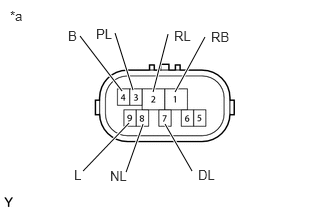
Tester Connection Condition Specified Condition 4 (B) - 9 (L) Shift lever in P or N Below 1 Ω 1 (RB) - 3 (PL) Shift lever in P Below 1 Ω 1 (RB) - 2 (RL) Shift lever in R Below 1 Ω 1 (RB) - 8 (NL) Shift lever in N Below 1 Ω 1 (RB) - 7 (DL) Shift lever in D, M, "+" or "-" Below 1 Ω 4 (B) - 9 (L) Shift lever not in P or N 10 kΩ or higher 1 (RB) - 3 (PL) Shift lever not in P 10 kΩ or higher 1 (RB) - 2 (RL) Shift lever not in R 10 kΩ or higher 1 (RB) - 8 (NL) Shift lever not in N 10 kΩ or higher 1 (RB) - 7 (DL) Shift lever not in D, M, "+" or "-" 10 kΩ or higher Result
Proceed to OK NG
Result:
NG
REPLACE PARK/NEUTRAL POSITION SWITCH ASSEMBLY. Refer to COMPONENTS [12/2019 - 10/2022]
Result:
OK
See step 4
- Disconnect the C52 park/neutral position switch assembly connector.
- CHECK HARNESS AND CONNECTOR (PARK/NEUTRAL POSITION SWITCH ASSEMBLY - ECM)
- Connect the C52 park/neutral position switch assembly connector.
- Disconnect the C54 ECM connector.
- Turn the ignition switch to ON.
- Measure the voltage according to the value(s) in the table below.
Standard Voltage
Tester Connection Condition Specified Condition C54-108 (P) - Body ground - Ignition switch ON
- Shift lever in P
11 to 14 V C54-107 (R) - Body ground - Ignition switch ON
- Shift lever in R
11 to 14 V* C54-140 (N) - Body ground - Ignition switch ON
- Shift lever in N
11 to 14 V C54-139 (D) - Body ground - Ignition switch ON
- Shift lever in D, M, "+" or "-"
11 to 14 V C54-108 (P) - Body ground - Ignition switch ON
- Shift lever not in P
Below 1 V C54-107 (R) - Body ground - Ignition switch ON
- Shift lever not in R
Below 1 V C54-140 (N) - Body ground - Ignition switch ON
- Shift lever not in N
Below 1 V C54-139 (D) - Body ground - Ignition switch ON
- Shift lever not in D, M, "+" or "-"
Below 1 V HINT:
*: The voltage will drop slightly due to the illumination of the back up lights.
Result
Proceed to OK NG
Result:
NG
REPAIR OR REPLACE HARNESS OR CONNECTOR (PARK/NEUTRAL POSITION SWITCH ASSEMBLY - ECM)
Result:
OK
See step 5
- REPLACE ECM
- Replace the ECM.
Refer to COMPONENTS [12/2019 - 10/2022]
Result
Proceed to NEXT
Result:
NEXT
PERFORM REGISTRATION. Refer to REGISTRATION [12/2019 - 10/2022]
- Replace the ECM.
- CHECK HARNESS AND CONNECTOR (PARK/NEUTRAL POSITION SWITCH ASSEMBLY - ECM)
- Disconnect the C52 park/neutral position switch assembly connector.
- Disconnect the C54 ECM connector.
- Measure the resistance according to the value(s) in the table below.
Standard Resistance
Tester Connection Condition Specified Condition C52-4 (B) - C54-106 (NSW) Always Below 1 Ω C52-4 (B) or C54-106 (NSW) - Body ground and other terminals Always 10 kΩ or higher Result
Proceed to OK NG
Result:
NG
REPAIR OR REPLACE HARNESS OR CONNECTOR (PARK/NEUTRAL POSITION SWITCH ASSEMBLY - ECM)
Result:
OK
See step 7
- REPLACE ECM
- Replace the ECM.
Refer to COMPONENTS [12/2019 - 10/2022]
Result
Proceed to NEXT
Result:
NEXT
PERFORM REGISTRATION. Refer to REGISTRATION [12/2019 - 10/2022]
- Replace the ECM.