DTC P0615-12: Starter Relay Circuit Short to Battery [12/2019 - 10/2022]: Procedure
- READ VALUE USING GTS (STARTER SW)
- Read the Data List according to the display on the GTS.
Powertrain > Transmission > Data List
Tester Display Measurement Item Range Normal Condition Diagnostic Note Starter SW Starter signal OFF or ON - ON: Starter operating
- OFF: Starter not operating
- Powertrain > Transmission > Data List
Tester Display Starter SW OK
Condition Starter SW Ignition switch ON OFF - Read the Data List according to the display on the GTS while the vehicle is being driven with an engine speed of 1000 rpm or more at a vehicle speed of 20 km/h (12 mph) or more.
OK
Condition Starter SW Driving at 20 km/h (12 mph) or more (engine speed 1000 rpm or more) OFF HINT:
If the result of either of the above is not as specified, proceed to the next step with the ignition switch ON, the GTS connected and Data List item "Starter SW" selected.
Result
Proceed to OK NG HINT:
If the starter assembly operates continuously when the ignition switch is turned to ON, proceed to the next step without reading the Data List item "Starter SW".
Result:
OK
SYMPTOMS SIMULATION AND DTC CHECK. Refer to HOW TO PROCEED WITH TROUBLESHOOTING [12/2019 - ]
Result:
NG
See step 2
- Read the Data List according to the display on the GTS.
- INSPECT ST RELAY (CHECK FOR SHORT CIRCUIT)
- Read the Data List according to the display on the GTS.
Powertrain > Transmission > Data List
Tester Display Measurement Item Range Normal Condition Diagnostic Note Starter SW Starter signal OFF or ON - ON: Starter operating
- OFF: Starter not operating
- Powertrain > Transmission > Data List
Tester Display Starter SW - Remove the ST relay from the No. 1 engine room relay block and No. 1 junction block assembly.
- Read the Data List according to the display on the GTS again.
Result
Result Proceed to The Data List item "Starter SW" does not change from ON. A The Data List item "Starter SW" changes from ON to OFF. B HINT:
- When the result of the above inspection is "The Data List item "Starter SW" does not change from ON", the ST relay is normal.
- DTCs may be stored during this inspection. Check for DTCs and clear them using the GTS.
Result:
B
REPLACE ST RELAY
Result:
A
See step 3
- Read the Data List according to the display on the GTS.
- CHECK TERMINAL VOLTAGE (POWER SOURCE OF ST RELAY)
HINT:
The purpose of this step is to check for ST relay terminal voltage under abnormal conditions.
- Remove the ST relay from the No. 1 engine room relay block and No. 1 junction block assembly.
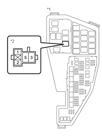
*1 No. 1 Engine Room Relay Block and No. 1 Junction Block Assembly *2 ST Relay Holder - Turn the ignition switch to ON.
- Measure the voltage between ST relay terminal 2 and body ground.
HINT:
- Make a note of the measured voltage as it will be necessary for inspecting the change in voltage in the next step. As the next step should be conducted under the same conditions, keep the ignition switch ON and do not install the ST relay.
- DTCs may be stored during this inspection. Check for DTCs and clear them using the GTS.
- If any voltage was measured with the ignition switch ON, one of the following malfunctions is suspected:
- Short to +B in the circuit of a connected ECU or park/neutral position switch assembly.
- Short to +B in the wire harness.
Result
Proceed to NEXT
Result:
NEXT
See step 4
- Remove the ST relay from the No. 1 engine room relay block and No. 1 junction block assembly.
- INSPECT PARK/NEUTRAL POSITION SWITCH ASSEMBLY (CHECK FOR SHORT CIRCUIT)
- Disconnect the C52 park/neutral position switch assembly connector.
*1 No. 1 Engine Room Relay Block and No. 1 Junction Block Assembly *2 ST Relay Holder - Measure the voltage between ST relay terminal 2 and body ground and compare it to the voltage measured in the previous step.
Result
Result Proceed to The voltage between ST relay terminal 2 and body ground does not change when the connector is disconnected (w/o Stop and Start System). A The voltage between ST relay terminal 2 and body ground does not change when the connector is disconnected (w/ Stop and Start System). B The voltage between ST relay terminal 2 and body ground changes when the connector is disconnected. C HINT:
- If the voltage is the same before and after disconnecting the connector, the park/neutral position switch assembly is normal.
- DTCs may be stored during this inspection. Check for DTCs and clear them using the GTS.
Result:
B
See step 8
Result:
C
REPLACE PARK/NEUTRAL POSITION SWITCH ASSEMBLY. Refer to COMPONENTS [12/2019 - 10/2022]
Result:
A
See step 5
- Disconnect the C52 park/neutral position switch assembly connector.
- INSPECT ECM (CHECK FOR SHORT CIRCUIT)
- Disconnect the A28 ECM connector.
*1 No. 1 Engine Room Relay Block and No. 1 Junction Block Assembly *2 ST Relay Holder - Measure the voltage between ST relay terminal 2 and body ground and compare it to the voltage measured in the previous step.
Result
Result Proceed to The voltage between ST relay terminal 2 and body ground does not change when the connector is disconnected. A The voltage between ST relay terminal 2 and body ground changes when the connector is disconnected. B HINT:
- If the voltage is the same before and after disconnecting the connector, the ECM is normal.
- DTCs may be stored during this inspection. Check for DTCs and clear them using the GTS.
Result:
B
See step 7
Result:
A
See step 6
- Disconnect the A28 ECM connector.
- CHECK HARNESS AND CONNECTOR (ECM - PARK/NEUTRAL POSITION SWITCH ASSEMBLY - SMART KEY ECU ASSEMBLY - ST RELAY)
- Disconnect the A28 ECM connector.
- Disconnect the C52 park/neutral position switch assembly connector.
- Disconnect the A19 certification ECU (smart key ECU assembly) connector.
- Remove the ST relay from the No. 1 engine room relay block and No. 1 junction block assembly.
- Measure the resistance according to the value(s) in the table below.
Standard Resistance
Tester Connection Condition Specified Condition A28-43 (STA), C52-9 (L), A19-20 (STA) or 2 (ST relay) - Other terminals Always 10 kΩ or higher Result
Proceed to OK NG
Result:
OK
CHECK SMART KEY SYSTEM (CHECK FOR STA TERMINAL VOLTAGE OF SMART KEY ECU ASSEMBLY). Refer to TERMINALS OF ECU [12/2019 - 10/2021] , or refer to TERMINALS OF ECU [10/2021 - 10/2022]
Result:
NG
REPAIR OR REPLACE HARNESS OR CONNECTOR
- REPLACE ECM
- Replace the ECM.
Refer to COMPONENTS [12/2019 - 10/2022]
Result
Proceed to NEXT
Result:
NEXT
PERFORM REGISTRATION. Refer to REGISTRATION [12/2019 - 10/2022]
- Replace the ECM.
- INSPECT ENGINE STOP AND START ECU (CHECK FOR SHORT CIRCUIT)
- Disconnect the A34 engine stop and start ECU connector.
*1 No. 1 Engine Room Relay Block and No. 1 Junction Block Assembly *2 ST Relay Holder - Measure the voltage between ST relay terminal 2 and body ground and compare it to the voltage measured in the previous step.
Result
Result Proceed to The voltage between ST relay terminal 2 and body ground does not change when the connector is disconnected. A The voltage between ST relay terminal 2 and body ground changes when the connector is disconnected. B HINT:
- If the voltage is the same before and after disconnecting the connector, the engine stop and start ECU is normal.
- DTCs may be stored during this inspection. Check for DTCs and clear them using the GTS.
Result:
B
REPLACE ENGINE STOP AND START ECU. Refer to COMPONENTS [12/2019 - ]
Result:
A
See step 9
- Disconnect the A34 engine stop and start ECU connector.
- INSPECT ECM (CHECK FOR SHORT CIRCUIT)
- Disconnect the A28 ECM connector.
*1 No. 1 Engine Room Relay Block and No. 1 Junction Block Assembly *2 ST Relay Holder - Measure the voltage between ST relay terminal 2 and body ground and compare it to the voltage measured in the previous step.
Result
Result Proceed to The voltage between ST relay terminal 2 and body ground does not change when the connector is disconnected. A The voltage between ST relay terminal 2 and body ground changes when the connector is disconnected. B HINT:
- If the voltage is the same before and after disconnecting the connector, the ECM is normal.
- DTCs may be stored during this inspection. Check for DTCs and clear them using the GTS.
Result:
B
See step 11
Result:
A
See step 10
- Disconnect the A28 ECM connector.
- CHECK HARNESS AND CONNECTOR (ECM - PARK/NEUTRAL POSITION SWITCH ASSEMBLY - ENGINE STOP AND START ECU - SMART KEY ECU ASSEMBLY - ST RELAY)
- Disconnect the A28 ECM connector.
- Disconnect the C52 park/neutral position switch assembly connector.
- Disconnect the A19 certification ECU (smart key ECU assembly) connector.
- Disconnect the A34 engine stop and start ECU connector.
- Remove the ST relay from the No. 1 engine room relay block and No. 1 junction block assembly.
- Measure the resistance according to the value(s) in the table below.
Standard Resistance
Tester Connection Condition Specified Condition A28-43 (STA), C52-9 (L), A19-20 (STA), A34-21 (STA) or 2 (ST relay) - Other terminals Always 10 kΩ or higher Result
Proceed to OK NG
Result:
OK
CHECK SMART KEY SYSTEM (CHECK FOR STA TERMINAL VOLTAGE OF SMART KEY ECU ASSEMBLY). Refer to TERMINALS OF ECU [12/2019 - 10/2021] , or refer to TERMINALS OF ECU [10/2021 - 10/2022]
Result:
NG
REPAIR OR REPLACE HARNESS OR CONNECTOR
- REPLACE ECM
- Replace the ECM.
Refer to COMPONENTS [12/2019 - 10/2022]
Result
Proceed to NEXT
Result:
NEXT
PERFORM REGISTRATION. Refer to REGISTRATION [12/2019 - 10/2022]
- Replace the ECM.