Buzzer does not Sound [12/2019 - 11/2023]: Procedure
- READ VALUE USING GTS
- Connect the GTS to the DLC3.
- Turn the ignition switch to ON.
- Turn the GTS on.
- Enter the following menus: Body Electrical / Blind Spot Monitor Slave / Data List.
- Read the Data List according to the display on the GTS.
Body Electrical > Blind Spot Monitor Slave > Data List
Tester Display Measurement Item Range Normal Condition Diagnostic Note Buzzer Connection Connection status of the buzzer Valid or Invalid Valid: Connection
Invalid: No connection- Slave Side RCTA Function Switches the RCTA function on and off OFF or ON OFF: RCTA function off
ON: RCTA function on- Body Electrical > Blind Spot Monitor Slave > Data List
Tester Display Buzzer Connection Slave Side RCTA Function Result
Result Proceed to "Valid" and "ON" is displayed for all items. A "Invalid" or "OFF" is displayed. B
Result:
B
REPLACE BLIND SPOT MONITOR SENSOR RH (A). Refer to REMOVAL [12/2019 - 10/2022] , or refer to REMOVAL [10/2022 - 11/2023]
Result:
A
See step 2
- CHECK FOR DTC
- According to the display on the GTS, check for DTCs.
Body Electrical > Blind Spot Monitor Slave > Clear DTCs
- According to the display on the GTS, check for DTCs.
Body Electrical > Blind Spot Monitor Slave > Trouble Codes
OK
No DTCs are output.
Result
Proceed to OK NG
Result:
NG
GO TO BLIND SPOT MONITOR SYSTEM. Refer to DIAGNOSTIC TROUBLE CODE CHART [12/2019 - 11/2023]
Result:
OK
See step 3
- According to the display on the GTS, check for DTCs.
- CHECK HARNESS AND CONNECTOR (RCTA BUZZER (BLIND SPOT MONITOR BUZZER) - BLIND SPOT MONITOR SENSOR RH (A) AND POWER SOURCE)
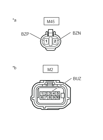
- Disconnect the M45 RCTA buzzer (blind spot monitor buzzer) connector.
*a Front view of wire harness connector
(to RCTA Buzzer (Blind Spot Monitor Buzzer))*b Front view of wire harness connector
(to Blind Spot Monitor Sensor RH (A)) - Disconnect the M2 blind spot monitor sensor RH (A) connector.
- Measure the voltage according to the value(s) in the table below.
Standard Voltage
Tester Connection Switch Condition Specified Condition M45-1 (BZP) - Body ground Ignition switch ON 11 to 14 V M45-2 (BZN) or M2-3 (BUZ) - Body ground Ignition switch ON Below 1 V M45-2 (BZN) - M45-1 (BZP) Ignition switch ON Below 1 V Result
Proceed to OK NG
Result:
NG
REPAIR OR REPLACE HARNESS OR CONNECTOR
Result:
OK
See step 4
- Disconnect the M45 RCTA buzzer (blind spot monitor buzzer) connector.
- CHECK HARNESS AND CONNECTOR (RCTA BUZZER (BLIND SPOT MONITOR BUZZER) - BLIND SPOT MONITOR SENSOR RH (A) AND AUXILIARY BATTERY)
- Disconnect the M45 RCTA buzzer (blind spot monitor buzzer) connector.
- Disconnect the M2 blind spot monitor sensor RH (A) connector.
- Measure the resistance according to the value(s) in the table below.
Standard Resistance
Tester Connection Condition Specified Condition M45-2 (BZN) - M2-3 (BUZ) Always Below 1 Ω M45-2 (BZN) or M2-3 (BUZ) - Body ground Always 10 kΩ or higher Result
Proceed to OK NG
Result:
OK
REPLACE RCTA BUZZER (BLIND SPOT MONITOR BUZZER). Refer to REMOVAL [12/2019 - ]
Result:
NG
REPAIR OR REPLACE HARNESS OR CONNECTOR