DTC P0715-12: Input/Turbine Speed Sensor "A" Circuit Short to Battery; DTC P0715-14: Input/Turbine Speed Sensor "A" Circuit Short to Ground or Open; DTC P0715-31: Input/Turbine Speed Sensor "A" No Signal [12/2019 - 10/2022]: Procedure
WARNING: This page is about a different variant/trim than selected.
- READ VALUE USING GTS
- Read the Data List according to the display on the GTS.
Powertrain > Transmission > Data List
Tester Display Measurement Item Range Normal Condition Diagnostic Note NT Sensor Speed Input shaft speed Min.: 0 rpm
Max.: 12750 rpm- Equal to engine speed: Lock-up on (after warming up engine)
- Nearly equal to engine speed: Lock-up off (idling with shift lever in N)
Data is displayed in increments of 50 rpm NT Sensor Voltage NT sensor voltage Min.: 0.000 V
Max.: 4.999 V0.1 to 1.9 V: Engine idling - Powertrain > Transmission > Data List
Tester Display NT Sensor Speed NT Sensor Voltage Result
Result Proceed to Data List values are normal A Data List values are not normal B
Result:
A
See step 5
Result:
B
See step 2
- Read the Data List according to the display on the GTS.
- INSPECT TRANSMISSION REVOLUTION SENSOR (NT)
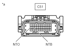
- Disconnect the C51 transmission wire connector.
*a Front view of wire harness connector
(to Transmission Wire) - Measure the resistance according to the value(s) in the table below.
Standard Resistance
Tester Connection Condition Specified Condition C51-11 (NTO) - Body ground Always 99 to 101 Ω - Turn the ignition switch to ON.
- Measure the voltage according to the value(s) in the table below.
Standard Voltage
Tester Connection Condition Specified Condition C51-12 (NTB) - Body ground Ignition switch ON 11 to 14 V Result
Proceed to OK NG
Result:
NG
See step 4
Result:
OK
See step 3
- Disconnect the C51 transmission wire connector.
- INSPECT TRANSMISSION WIRE (TRANSMISSION REVOLUTION SENSOR (NT))
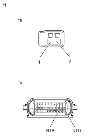
- Disconnect the transmission revolution sensor (NT) connector.
*1 Transmission Wire *a Transmission Revolution Sensor (NT) Side *b Wire Harness Connector Side Refer to REMOVAL [12/2019 - 10/2022]
- Disconnect the C51 transmission wire connector.
- Measure the resistance according to the value(s) in the table below.
Standard Resistance
Tester Connection Condition Specified Condition 1 (transmission revolution sensor (NT) side) - 12 (NTB) (wire harness connector side) Always Below 1 Ω 2 (transmission revolution sensor (NT) side) - 11 (NTO) (wire harness connector side) Always Below 1 Ω 1 (transmission revolution sensor (NT) side) or 12 (NTB) (wire harness connector side) - Body ground and other terminals Always 10 kΩ or higher 2 (transmission revolution sensor (NT) side) or 11 (NTO) (wire harness connector side) - Body ground and other terminals Always 10 kΩ or higher Result
Proceed to OK NG
Result:
OK
REPLACE TRANSMISSION REVOLUTION SENSOR (NT). Refer to COMPONENTS [12/2019 - 10/2022]
Result:
NG
REPAIR OR REPLACE TRANSMISSION WIRE. Refer to COMPONENTS [12/2019 - 10/2022]
- Disconnect the transmission revolution sensor (NT) connector.
- CHECK HARNESS AND CONNECTOR (TRANSMISSION WIRE - ECM)
- Disconnect the C51 transmission wire connector.
- Disconnect the C54 ECM connector.
- Measure the resistance according to the value(s) in the table below.
Standard Resistance
Tester Connection Condition Specified Condition C51-12 (NTB) - C54-75 (NTB) Always Below 1 Ω C51-11 (NTO) - C54-74 (NTO) Always Below 1 Ω C51-12 (NTB) or C54-75 (NTB) - Body ground and other terminals Always 10 kΩ or higher C51-11 (NTO) or C54-74 (NTO) - Body ground and other terminals Always 10 kΩ or higher Result
Proceed to OK NG
Result:
NG
REPAIR OR REPLACE HARNESS OR CONNECTOR (TRANSMISSION WIRE - ECM)
Result:
OK
See step 5
- REPLACE ECM
- Replace the ECM.
Refer to COMPONENTS [12/2019 - 10/2022]
Result
Proceed to NEXT
Result:
NEXT
PERFORM REGISTRATION. Refer to REGISTRATION [12/2019 - 10/2022]
- Replace the ECM.