Terminals Of Ecu [12/2019 - 11/2023]
- CHECK MULTIPLEX NETWORK MASTER SWITCH ASSEMBLY
- Disconnect the J18 multiplex network master switch assembly connector.
- Measure the voltage and resistance according to the value(s) in the table below.
HINT:
Measure the values on the wire harness side with the connector disconnected.
Terminal No. (Symbol) Terminal Description Condition Specified Condition J18-11 (B) - J18-12 (GND) Power supply Always*1 11 to 14 V Ignition switch off*2 J18-12 (GND) - Body ground Ground Always Below 1 Ω - *1: for Gasoline Model
- *2: for HV Model
- Reconnect the J18 multiplex network master switch assembly connector.
- Measure the voltage according to the value(s) in the table below.
Terminal No. (Symbol) Terminal Description Condition Specified Condition J18-15 (DOWN) - J18-12 (GND) Power window motor DOWN output Ignition switch ON, driver door power window regulator switch not pushed or not pulled 11 to 14 V J18-15 (DOWN) - J18-12 (GND) Power window motor DOWN output Ignition switch ON, driver door power window moving, driver door power window regulator switch pushed halfway down (Manual operation) Below 1 V J18-20 (UP) - J18-12 (GND) Power window motor UP output Ignition switch ON, driver door power window regulator switch not pushed or not pulled 11 to 14 V J18-20 (UP) - J18-12 (GND) Power window motor UP output Ignition switch ON, driver door power window moving, driver door power window regulator switch pulled halfway up (Manual operation) Below 1 V
- CHECK POWER WINDOW REGULATOR SWITCH ASSEMBLY
- Disconnect the J3 power window regulator switch assembly connector.
- Measure the resistance according to the value(s) in the table below.
HINT:
Measure the values on the wire harness side with the connector disconnected.
Terminal No. (Symbol) Terminal Description Condition Specified Condition J3-7 (GND) - Body ground Ground Always Below 1 Ω - Reconnect the J3 power window regulator switch assembly connector.
- Measure the voltage according to the value(s) in the table below.
Terminal No. (Symbol) Terminal Description Condition Specified Condition J3-5 (UP) - J3-7 (GND) Power window motor UP output Ignition switch ON, power window regulator switch assembly not pushed or not pulled 11 to 14 V J3-5 (UP) - J3-7 (GND) Power window motor UP output Ignition switch ON, front passenger door power window moving, power window regulator switch assembly pulled halfway up (Manual operation) Below 1 V J3-5 (UP) - J3-7 (GND) Power window motor UP output Ignition switch ON, front passenger door power window fully open 11 to 14 V J3-5 (UP) - J3-7 (GND) Power window motor UP output Ignition switch ON, front passenger door power window moving, power window regulator switch assembly fully pulled up (Auto operation) Below 1 V J3-5 (UP) - J3-7 (GND) Power window motor UP output Ignition switch ON, front passenger door power window fully closed 11 to 14 V J3-4 (DOWN) - J3-7 (GND) Power window motor DOWN output Ignition switch ON, power window regulator switch assembly not pushed or not pulled 11 to 14 V J3-4 (DOWN) - J3-7 (GND) Power window motor DOWN output Ignition switch ON, front passenger door power window moving, power window regulator switch assembly pushed halfway down (Manual operation) Below 1 V J3-4 (DOWN) - J3-7 (GND) Power window motor DOWN output Ignition switch ON, front passenger door power window fully closed 11 to 14 V J3-4 (DOWN) - J3-7 (GND) Power window motor DOWN output Ignition switch ON, front passenger door power window moving, power window regulator switch assembly fully pushed down (Auto operation) Below 1 V J3-4 (DOWN) - J3-7 (GND) Power window motor DOWN output Ignition switch ON, front passenger door power window fully open 11 to 14 V J3-8 (AUTO) - J3-7 (GND) Power window motor AUTO UP output Ignition switch ON, front passenger door power window fully open 11 to 14 V J3-8 (AUTO) - J3-7 (GND) Power window motor AUTO UP output Ignition switch ON, front passenger door power window moving, power window regulator switch assembly fully pulled up (Auto operation) Below 1 V J3-8 (AUTO) - J3-7 (GND) Power window motor AUTO UP output Ignition switch ON, front passenger door power window fully closed 11 to 14 V J3-8 (AUTO) - J3-7 (GND) Power window motor AUTO DOWN output Ignition switch ON, front passenger door power window fully closed 11 to 14 V J3-8 (AUTO) - J3-7 (GND) Power window motor AUTO DOWN output Ignition switch ON, front passenger door power window moving, power window regulator switch assembly fully pushed down (Auto operation) Below 1 V J3-8 (AUTO) - J3-7 (GND) Power window motor AUTO DOWN output Ignition switch ON, front passenger door power window fully open 11 to 14 V
- CHECK REAR POWER WINDOW REGULATOR SWITCH ASSEMBLY (FOR LH DOOR)
- Disconnect the K7 rear power window regulator switch assembly (for LH door) connector.
- Measure the resistance according to the value(s) in the table below.
HINT:
Measure the values on the wire harness side with the connector disconnected.
Terminal No. (Symbol) Terminal Description Condition Specified Condition K7-7 (GND) - Body ground Ground Always Below 1 Ω - Reconnect the K7 rear power window regulator switch assembly (for LH door) connector.
- Measure the voltage according to the value(s) in the table below.
Terminal No. (Symbol) Terminal Description Condition Specified Condition K7-5 (UP) - K7-7 (GND) Power window motor UP output Ignition switch ON, rear power window regulator switch assembly (for LH door) not pushed or not pulled 11 to 14 V K7-5 (UP) - K7-7 (GND) Power window motor UP output Ignition switch ON, rear LH door power window moving, rear power window regulator switch assembly (for LH door) pulled halfway up (Manual operation) Below 1 V K7-5 (UP) - K7-7 (GND) Power window motor UP output Ignition switch ON, rear LH door power window fully open 11 to 14 V K7-5 (UP) - K7-7 (GND) Power window motor UP output Ignition switch ON, rear LH door power window moving, rear power window regulator switch assembly (for LH door) fully pulled up (Auto operation) Below 1 V K7-5 (UP) - K7-7 (GND) Power window motor UP output Ignition switch ON, rear LH door power window fully closed 11 to 14 V K7-4 (DOWN) - K7-7 (GND) Power window motor DOWN output Ignition switch ON, rear power window regulator switch assembly (for LH door) not pushed or not pulled 11 to 14 V K7-4 (DOWN) - K7-7 (GND) Power window motor DOWN output Ignition switch ON, rear LH door power window moving, rear power window regulator switch assembly (for LH door) pushed halfway down (Manual operation) Below 1 V K7-4 (DOWN) - K7-7 (GND) Power window motor DOWN output Ignition switch ON, rear LH door power window fully closed 11 to 14 V K7-4 (DOWN) - K7-7 (GND) Power window motor DOWN output Ignition switch ON, rear LH door power window moving, rear power window regulator switch assembly (for LH door) fully pushed down (Auto operation) Below 1 V K7-4 (DOWN) - K7-7 (GND) Power window motor DOWN output Ignition switch ON, rear LH door power window fully open 11 to 14 V K7-8 (AUTO) - K7-7 (GND) Power window motor AUTO UP output Ignition switch ON, rear LH door power window fully open 11 to 14 V K7-8 (AUTO) - K7-7 (GND) Power window motor AUTO UP output Ignition switch ON, rear LH door power window moving, rear power window regulator switch assembly (for LH door) fully pulled up (Auto operation) Below 1 V K7-8 (AUTO) - K7-7 (GND) Power window motor AUTO UP output Ignition switch ON, rear LH door power window fully closed 11 to 14 V K7-8 (AUTO) - K7-7 (GND) Power window motor AUTO DOWN output Ignition switch ON, rear LH door power window fully closed 11 to 14 V K7-8 (AUTO) - K7-7 (GND) Power window motor AUTO DOWN output Ignition switch ON, rear LH door power window moving, rear power window regulator switch assembly (for LH door) fully pushed down (Auto operation) Below 1 V K7-8 (AUTO) - K7-7 (GND) Power window motor AUTO DOWN output Ignition switch ON, rear LH door power window fully open 11 to 14 V
- CHECK REAR POWER WINDOW REGULATOR SWITCH ASSEMBLY (FOR RH DOOR)
- Disconnect the K2 rear power window regulator switch assembly (for RH door) connector.
- Measure the resistance according to the value(s) in the table below.
HINT:
Measure the values on the wire harness side with the connector disconnected.
Terminal No. (Symbol) Terminal Description Condition Specified Condition K2-7 (GND) - Body ground Ground Always Below 1 Ω - Reconnect the K2 rear power window regulator switch assembly (for RH door) connector.
- Measure the voltage according to the value(s) in the table below.
Terminal No. (Symbol) Terminal Description Condition Specified Condition K2-5 (UP) - K2-7 (GND) Power window motor UP output Ignition switch ON, rear power window regulator switch assembly (for RH door) not pushed or not pulled 11 to 14 V K2-5 (UP) - K2-7 (GND) Power window motor UP output Ignition switch ON, rear RH door power window moving, rear power window regulator switch assembly (for RH door) pulled halfway up (Manual operation) Below 1 V K2-5 (UP) - K2-7 (GND) Power window motor UP output Ignition switch ON, rear RH door power window fully open 11 to 14 V K2-5 (UP) - K2-7 (GND) Power window motor UP output Ignition switch ON, rear RH door power window moving, rear power window regulator switch assembly (for RH door) fully pulled up (Auto operation) Below 1 V K2-5 (UP) - K2-7 (GND) Power window motor UP output Ignition switch ON, rear RH door power window fully closed 11 to 14 V K2-4 (DOWN) - K2-7 (GND) Power window motor DOWN output Ignition switch ON, rear power window regulator switch assembly (for RH door) not pushed or not pulled 11 to 14 V K2-4 (DOWN) - K2-7 (GND) Power window motor DOWN output Ignition switch ON, rear RH door power window moving, rear power window regulator switch assembly (for RH door) pushed halfway down (Manual operation) Below 1 V K2-4 (DOWN) - K2-7 (GND) Power window motor DOWN output Ignition switch ON, rear RH door power window fully closed 11 to 14 V K2-4 (DOWN) - K2-7 (GND) Power window motor DOWN output Ignition switch ON, rear RH door power window moving, rear power window regulator switch assembly (for RH door) fully pushed down (Auto operation) Below 1 V K2-4 (DOWN) - K2-7 (GND) Power window motor DOWN output Ignition switch ON, rear RH door power window fully open 11 to 14 V K2-8 (AUTO) - K2-7 (GND) Power window motor AUTO UP output Ignition switch ON, rear RH door power window fully open 11 to 14 V K2-8 (AUTO) - K2-7 (GND) Power window motor AUTO UP output Ignition switch ON, rear RH door power window moving, rear power window regulator switch assembly (for RH door) fully pulled up (Auto operation) Below 1 V K2-8 (AUTO) - K2-7 (GND) Power window motor AUTO UP output Ignition switch ON, rear RH door power window fully closed 11 to 14 V K2-8 (AUTO) - K2-7 (GND) Power window motor AUTO DOWN output Ignition switch ON, rear RH door power window fully closed 11 to 14 V K2-8 (AUTO) - K2-7 (GND) Power window motor AUTO DOWN output Ignition switch ON, rear RH door power window moving, rear power window regulator switch assembly (for RH door) fully pushed down (Auto operation) Below 1 V K2-8 (AUTO) - K2-7 (GND) Power window motor AUTO DOWN output Ignition switch ON, rear RH door power window fully open 11 to 14 V
- CHECK POWER WINDOW REGULATOR MOTOR ASSEMBLY (FOR DRIVER DOOR)
- Disconnect the J24 power window regulator motor assembly (for driver door) connector.
- Measure the voltage and resistance according to the value(s) in the table below.
HINT:
Measure the values on the wire harness side with the connector disconnected.
Terminal No. (Symbol) Terminal Description Condition Specified Condition J24-1 (GND) - Body ground Ground Always Below 1 Ω J24-2 (B) - Body ground Power supply Always*1 11 to 14 V Ignition switch off*2 - *1: for Gasoline Model
- *2: for HV Model
- Reconnect the J24 power window regulator motor assembly (for driver door) connector.
- Measure the voltage according to the value(s) in the table below.
Terminal No. (Symbol) Terminal Description Condition Specified Condition J24-7 (DOWN) - J24-1 (GND) Power window motor DOWN input Ignition switch ON, multiplex network master switch assembly (driver door power window regulator switch) not pushed or not pulled 11 to 14 V J24-7 (DOWN) - J24-1 (GND) Power window motor DOWN input Ignition switch ON, driver door power window moving, multiplex network master switch assembly (driver door power window regulator switch) pushed halfway down (Manual operation) Below 1 V J24-7 (DOWN) - J24-1 (GND) Power window motor DOWN input Ignition switch ON, driver door power window fully closed 11 to 14 V J24-7 (DOWN) - J24-1 (GND) Power window motor DOWN input Ignition switch ON, driver door power window moving, multiplex network master switch assembly (driver door power window regulator switch) fully pushed down (Auto operation) Below 1 V J24-7 (DOWN) - J24-1 (GND) Power window motor DOWN input Ignition switch ON, driver door power window fully open 11 to 14 V J24-10 (UP) - J24-1 (GND) Power window motor UP input Ignition switch ON, multiplex network master switch assembly (driver door power window regulator switch) not pushed or not pulled 11 to 14 V J24-10 (UP) - J24-1 (GND) Power window motor UP input Ignition switch ON, driver door power window moving, multiplex network master switch assembly (driver door power window regulator switch) pulled halfway up (Manual operation) Below 1 V J24-10 (UP) - J24-1 (GND) Power window motor UP input Ignition switch ON, multiplex network master switch assembly (driver door power window regulator switch) fully open 11 to 14 V J24-10 (UP) - J24-1 (GND) Power window motor UP input Ignition switch ON, driver door power window moving, multiplex network master switch assembly (driver door power window regulator switch) fully pulled up (Auto operation) Below 1 V J24-10 (UP) - J24-1 (GND) Power window motor UP input Ignition switch ON, driver door power window fully closed 11 to 14 V
- CHECK POWER WINDOW REGULATOR MOTOR ASSEMBLY (FOR FRONT PASSENGER DOOR)
- Disconnect the J8 power window regulator motor assembly (for front passenger door) connector.
- Measure the voltage and resistance according to the value(s) in the table below.
HINT:
Measure the values on the wire harness side with the connector disconnected.
Terminal No. (Symbol) Terminal Description Condition Specified Condition J8-1 (GND) - Body ground Ground Always Below 1 Ω J8-2 (B) - Body ground Power supply Always*1 11 to 14 V Ignition switch off*2 - *1: for Gasoline Model
- *2: for HV Model
- Reconnect the J8 power window regulator motor assembly (for front passenger door) connector.
- Measure the voltage according to the value(s) in the table below.
Terminal No. (Symbol) Terminal Description Condition Specified Condition J8-4 (AUTO) - J8-1 (GND) Power window motor AUTO UP input Ignition switch ON, front passenger door power window fully open 11 to 14 V J8-4 (AUTO) - J8-1 (GND) Power window motor AUTO UP input Ignition switch ON, front passenger door power window moving, power window regulator switch assembly fully pulled up (Auto operation) Below 1 V J8-4 (AUTO) - J8-1 (GND) Power window motor AUTO UP input Ignition switch ON, front passenger door power window fully closed 11 to 14 V J8-4 (AUTO) - J8-1 (GND) Power window motor AUTO DOWN input Ignition switch ON, front passenger door power window fully closed 11 to 14 V J8-4 (AUTO) - J8-1 (GND) Power window motor AUTO DOWN input Ignition switch ON, front passenger door power window moving, power window regulator switch assembly fully pushed down (Auto operation) Below 1 V J8-4 (AUTO) - J8-1 (GND) Power window motor AUTO DOWN input Ignition switch ON, front passenger door power window fully open 11 to 14 V J8-7 (DOWN) - J8-1 (GND) Power window motor DOWN input Ignition switch ON, power window regulator switch assembly not pushed or not pulled 11 to 14 V J8-7 (DOWN) - J8-1 (GND) Power window motor DOWN input Ignition switch ON, front passenger door power window moving, power window regulator switch assembly pushed halfway down (Manual operation) Below 1 V J8-7 (DOWN) - J8-1 (GND) Power window motor DOWN input Ignition switch ON, front passenger door power window fully closed 11 to 14 V J8-7 (DOWN) - J8-1 (GND) Power window motor DOWN input Ignition switch ON, front passenger door power window moving, power window regulator switch assembly fully pushed down (Auto operation) Below 1 V J8-7 (DOWN) - J8-1 (GND) Power window motor DOWN input Ignition switch ON, front passenger door power window fully open 11 to 14 V J8-10 (UP) - J8-1 (GND) Power window motor UP input Ignition switch ON, power window regulator switch assembly not pushed or not pulled 11 to 14 V J8-10 (UP) - J8-1 (GND) Power window motor UP input Ignition switch ON, front passenger door power window moving, power window regulator switch assembly pulled halfway up (Manual operation) Below 1 V J8-10 (UP) - J8-1 (GND) Power window motor UP input Ignition switch ON, front passenger door power window fully open 11 to 14 V J8-10 (UP) - J8-1 (GND) Power window motor UP input Ignition switch ON, front passenger door power window moving, power window regulator switch assembly fully pulled up (Auto operation) Below 1 V J8-10 (UP) - J8-1 (GND) Power window motor UP input Ignition switch ON, front passenger door power window fully closed 11 to 14 V
- CHECK POWER WINDOW REGULATOR MOTOR ASSEMBLY (FOR REAR LH DOOR)
- Disconnect the K9 power window regulator motor assembly (for rear LH door) connector.
- Measure the voltage and resistance according to the value(s) in the table below.
HINT:
Measure the values on the wire harness side with the connector disconnected.
Terminal No. (Symbol) Terminal Description Condition Specified Condition K9-1 (GND) - Body ground Ground Always Below 1 Ω K9-2 (B) - Body ground Power supply Always*1 11 to 14 V Ignition switch off*2 - *1: for Gasoline Model
- *2: for HV Model
- Reconnect the K9 power window regulator motor assembly (for rear LH door) connector.
- Measure the voltage according to the value(s) in the table below.
Terminal No. (Symbol) Terminal Description Condition Specified Condition K9-4 (AUTO) - K9-1 (GND) Power window motor AUTO UP input Ignition switch ON, rear LH door power window fully open 11 to 14 V K9-4 (AUTO) - K9-1 (GND) Power window motor AUTO UP input Ignition switch ON, rear LH door power window moving, rear power window regulator switch assembly (for LH door) fully pulled up (Auto operation) Below 1 V K9-4 (AUTO) - K9-1 (GND) Power window motor AUTO UP input Ignition switch ON, rear LH door power window fully closed 11 to 14 V K9-4 (AUTO) - K9-1 (GND) Power window motor AUTO DOWN input Ignition switch ON, rear LH door power window fully closed 11 to 14 V K9-4 (AUTO) - K9-1 (GND) Power window motor AUTO DOWN input Ignition switch ON, rear LH door power window moving, rear power window regulator switch assembly (for LH door) fully pushed down (Auto operation) Below 1 V K9-4 (AUTO) - K9-1 (GND) Power window motor AUTO DOWN input Ignition switch ON, rear LH door power window fully open 11 to 14 V K9-7 (DOWN) - K9-1 (GND) Power window motor DOWN input Ignition switch ON, rear power window regulator switch assembly (for LH door) not pushed or not pulled 11 to 14 V K9-7 (DOWN) - K9-1 (GND) Power window motor DOWN input Ignition switch ON, rear LH door power window moving, rear power window regulator switch assembly (for LH door) pushed halfway down (Manual operation) Below 1 V K9-7 (DOWN) - K9-1 (GND) Power window motor DOWN input Ignition switch ON, rear LH door power window fully closed 11 to 14 V K9-7 (DOWN) - K9-1 (GND) Power window motor DOWN input Ignition switch ON, rear LH door power window moving, rear power window regulator switch assembly (for LH door) fully pushed down (Auto operation) Below 1 V K9-7 (DOWN) - K9-1 (GND) Power window motor DOWN input Ignition switch ON, rear LH door power window fully open 11 to 14 V K9-10 (UP) - K9-1 (GND) Power window motor UP input Ignition switch ON, rear power window regulator switch assembly (for LH door) not pushed or not pulled 11 to 14 V K9-10 (UP) - K9-1 (GND) Power window motor UP input Ignition switch ON, rear LH door power window moving, rear power window regulator switch assembly (for LH door) pulled halfway up (Manual operation) Below 1 V K9-10 (UP) - K9-1 (GND) Power window motor UP input Ignition switch ON, rear LH door power window fully open 11 to 14 V K9-10 (UP) - K9-1 (GND) Power window motor UP input Ignition switch ON, rear LH door power window moving, rear power window regulator switch assembly (for LH door) fully pulled up (Auto operation) Below 1 V K9-10 (UP) - K9-1 (GND) Power window motor UP input Ignition switch ON, rear LH door power window fully closed 11 to 14 V
- CHECK POWER WINDOW REGULATOR MOTOR ASSEMBLY (FOR REAR RH DOOR)
- Disconnect the K4 power window regulator motor assembly (for rear RH door) connector.
- Measure the voltage and resistance according to the value(s) in the table below.
HINT:
Measure the values on the wire harness side with the connector disconnected.
Terminal No. (Symbol) Terminal Description Condition Specified Condition K4-1 (GND) - Body ground Ground Always Below 1 Ω K4-2 (B) - Body ground Power supply Always*1 11 to 14 V Ignition switch off*2 - *1: for Gasoline Model
- *2: for HV Model
- Reconnect the K4 power window regulator motor assembly (for rear RH door) connector.
- Measure the voltage according to the value(s) in the table below.
Terminal No. (Symbol) Terminal Description Condition Specified Condition K4-4 (AUTO) - K4-1 (GND) Power window motor AUTO UP input Ignition switch ON, rear RH door power window fully open 11 to 14 V K4-4 (AUTO) - K4-1 (GND) Power window motor AUTO UP input Ignition switch ON, rear RH door power window moving, rear power window regulator switch assembly (for RH door) fully pulled up (Auto operation) Below 1 V K4-4 (AUTO) - K4-1 (GND) Power window motor AUTO UP input Ignition switch ON, rear RH door power window fully closed 11 to 14 V K4-4 (AUTO) - K4-1 (GND) Power window motor AUTO DOWN input Ignition switch ON, rear RH door power window fully closed 11 to 14 V K4-4 (AUTO) - K4-1 (GND) Power window motor AUTO DOWN input Ignition switch ON, rear RH door power window moving, rear power window regulator switch assembly (for RH door) fully pushed down (Auto operation) Below 1 V K4-4 (AUTO) - K4-1 (GND) Power window motor AUTO DOWN input Ignition switch ON, rear RH door power window fully open 11 to 14 V K4-7 (DOWN) - K4-1 (GND) Power window motor DOWN input Ignition switch ON, rear power window regulator switch assembly (for RH door) not pushed or not pulled 11 to 14 V K4-7 (DOWN) - K4-1 (GND) Power window motor DOWN input Ignition switch ON, rear RH door power window moving, rear power window regulator switch assembly (for RH door) pushed halfway down (Manual operation) Below 1 V K4-7 (DOWN) - K4-1 (GND) Power window motor DOWN input Ignition switch ON, rear RH door power window fully closed 11 to 14 V K4-7 (DOWN) - K4-1 (GND) Power window motor DOWN input Ignition switch ON, rear RH door power window moving, rear power window regulator switch assembly (for RH door) fully pushed down (Auto operation) Below 1 V K4-7 (DOWN) - K4-1 (GND) Power window motor DOWN input Ignition switch ON, rear RH door power window fully open 11 to 14 V K4-10 (UP) - K4-1 (GND) Power window motor UP input Ignition switch ON, rear power window regulator switch assembly (for RH door) not pushed or not pulled 11 to 14 V K4-10 (UP) - K4-1 (GND) Power window motor UP input Ignition switch ON, rear RH door power window moving, rear power window regulator switch assembly (for RH door) pulled halfway up (Manual operation) Below 1 V K4-10 (UP) - K4-1 (GND) Power window motor UP input Ignition switch ON, rear RH door power window fully open 11 to 14 V K4-10 (UP) - K4-1 (GND) Power window motor UP input Ignition switch ON, rear RH door power window moving, rear power window regulator switch assembly (for RH door) fully pulled up (Auto operation) Below 1 V K4-10 (UP) - K4-1 (GND) Power window motor UP input Ignition switch ON, rear RH door power window fully closed 11 to 14 V
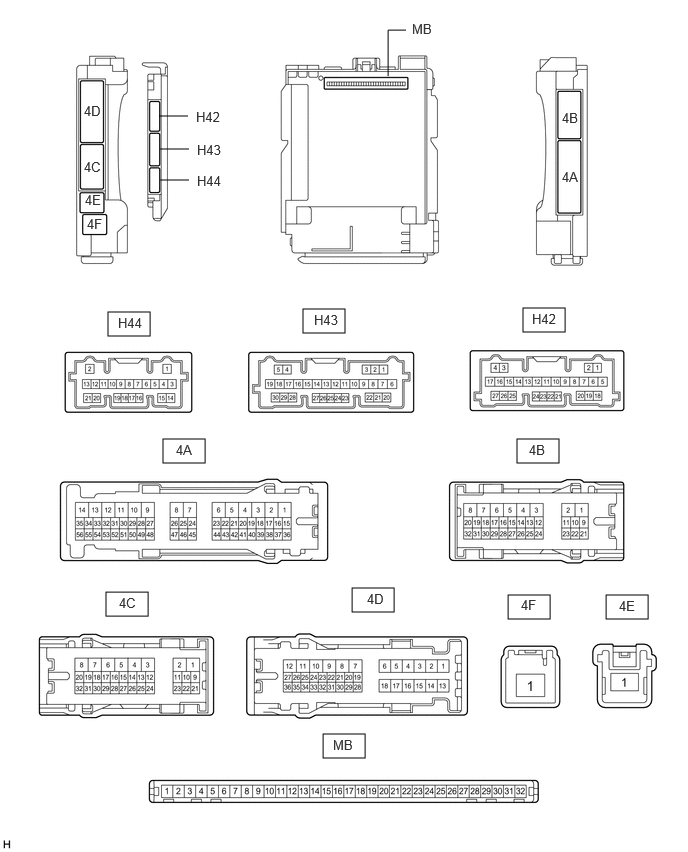
- CHECK INSTRUMENT PANEL JUNCTION BLOCK ASSEMBLY AND MAIN BODY ECU (MULTIPLEX NETWORK BODY ECU)
- Remove the main body ECU (multiplex network body ECU) from the instrument panel junction block assembly.
Refer to REMOVAL [12/2019 - 10/2022] , or refer to REMOVAL [10/2022 - 11/2023]
- Measure the resistance according to the value(s) in the table below.
HINT:
Measure the values on the wire harness side with the connectors connected.
Terminal No. (Symbol) Terminal Description Condition Specified Condition H42-19 (GND2) - Body ground Ground Always Below 1 Ω - Reconnect the instrument panel junction block assembly connectors.
- Measure the voltage and resistance according to the value(s) in the table below.
Terminal No. (Symbol) Terminal Description Condition Specified Condition MB-11 (GND1) - Body ground Ground Always Below 1 Ω MB-31 (BECU) - Body ground Auxiliary battery power supply Always*1 11 to 14 V Ignition switch off*2 MB-30 (ACC) - Body ground ACC power supply Ignition switch ACC 11 to 14 V MB-30 (ACC) - Body ground ACC power supply Ignition switch off Below 1 V MB-32 (IG) - Body ground IG power supply Ignition switch ON 11 to 14 V MB-32 (IG) - Body ground IG power supply Ignition switch off or ACC Below 1 V - *1: for Gasoline Model
- *2: for HV Model
- Install the main body ECU (multiplex network body ECU) to the instrument panel junction block assembly.
Refer to INSTALLATION [12/2019 - 10/2022] , or refer to INSTALLATION [10/2022 - 11/2023]
- Measure the voltage according to the value(s) in the table below.
Terminal No. (Symbol) Terminal Description Condition Specified Condition H43-1 (FLCY) - Body ground Front door courtesy light switch (for LH) input Front door LH open Below 1 V H43-1 (FLCY) - Body ground Front door courtesy light switch (for LH) input Front door LH closed 11 to 14 V H43-6 (FRCY) - Body ground Front door courtesy light switch (for RH) input Front door RH open Below 1 V H43-6 (FRCY) - Body ground Front door courtesy light switch (for RH) input Front door RH closed 11 to 14 V H44-18 (L2) - Body ground Driver door key-linked lock input Driver door key cylinder turned to lock Below 1 V H44-18 (L2) - Body ground Driver door key-linked lock input Driver door key cylinder not turned 11 to 14 V H44-17 (UL3) - Body ground Driver door key-linked unlock input Driver door key cylinder turned to unlock Below 1 V H44-17 (UL3) - Body ground Driver door key-linked unlock input Driver door key cylinder not turned 11 to 14 V
- Remove the main body ECU (multiplex network body ECU) from the instrument panel junction block assembly.