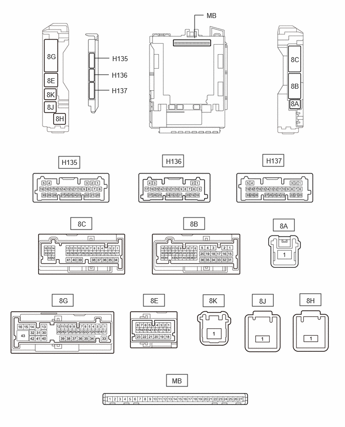
Terminals Of Ecu [11/2023 - ]
- CHECK MULTIPLEX NETWORK MASTER SWITCH ASSEMBLY
- Disconnect the J18 multiplex network master switch assembly connector.
- Measure the voltage and resistance according to the value(s) in the table below.
HINT:
Measure the values on the wire harness side with the connector disconnected.
Terminal No. (Symbol) Terminal Description Condition Specified Condition J18-11 (B) - J18-12 (GND) Power supply Always*1 11 to 14 V Ignition switch off*2 J18-12 (GND) - Body ground Ground Always Below 1 Ω - *1: for Gasoline Model
- *2: for HV Model
- Reconnect the J18 multiplex network master switch assembly connector.
- Measure the voltage according to the value(s) in the table below.
Terminal No. (Symbol) Terminal Description Condition Specified Condition J18-15 (DOWN) - J18-12 (GND) Power window motor DOWN output Ignition switch ON, driver door power window regulator switch not pushed or not pulled 11 to 14 V J18-15 (DOWN) - J18-12 (GND) Power window motor DOWN output Ignition switch ON, driver door power window moving, driver door power window regulator switch pushed halfway down (Manual operation) Below 1 V J18-20 (UP) - J18-12 (GND) Power window motor UP output Ignition switch ON, driver door power window regulator switch not pushed or not pulled 11 to 14 V J18-20 (UP) - J18-12 (GND) Power window motor UP output Ignition switch ON, driver door power window moving, driver door power window regulator switch pulled halfway up (Manual operation) Below 1 V
- CHECK POWER WINDOW REGULATOR SWITCH ASSEMBLY
- Disconnect the J3 power window regulator switch assembly connector.
- Measure the resistance according to the value(s) in the table below.
HINT:
Measure the values on the wire harness side with the connector disconnected.
Terminal No. (Symbol) Terminal Description Condition Specified Condition J3-7 (GND) - Body ground Ground Always Below 1 Ω - Reconnect the J3 power window regulator switch assembly connector.
- Measure the voltage according to the value(s) in the table below.
Terminal No. (Symbol) Terminal Description Condition Specified Condition J3-5 (UP) - J3-7 (GND) Power window motor UP output Ignition switch ON, power window regulator switch assembly not pushed or not pulled 11 to 14 V J3-5 (UP) - J3-7 (GND) Power window motor UP output Ignition switch ON, front passenger door power window moving, power window regulator switch assembly pulled halfway up (Manual operation) Below 1 V J3-5 (UP) - J3-7 (GND) Power window motor UP output Ignition switch ON, front passenger door power window fully open 11 to 14 V J3-5 (UP) - J3-7 (GND) Power window motor UP output Ignition switch ON, front passenger door power window moving, power window regulator switch assembly fully pulled up (Auto operation) Below 1 V J3-5 (UP) - J3-7 (GND) Power window motor UP output Ignition switch ON, front passenger door power window fully closed 11 to 14 V J3-4 (DOWN) - J3-7 (GND) Power window motor DOWN output Ignition switch ON, power window regulator switch assembly not pushed or not pulled 11 to 14 V J3-4 (DOWN) - J3-7 (GND) Power window motor DOWN output Ignition switch ON, front passenger door power window moving, power window regulator switch assembly pushed halfway down (Manual operation) Below 1 V J3-4 (DOWN) - J3-7 (GND) Power window motor DOWN output Ignition switch ON, front passenger door power window fully closed 11 to 14 V J3-4 (DOWN) - J3-7 (GND) Power window motor DOWN output Ignition switch ON, front passenger door power window moving, power window regulator switch assembly fully pushed down (Auto operation) Below 1 V J3-4 (DOWN) - J3-7 (GND) Power window motor DOWN output Ignition switch ON, front passenger door power window fully open 11 to 14 V J3-8 (AUTO) - J3-7 (GND) Power window motor AUTO UP output Ignition switch ON, front passenger door power window fully open 11 to 14 V J3-8 (AUTO) - J3-7 (GND) Power window motor AUTO UP output Ignition switch ON, front passenger door power window moving, power window regulator switch assembly fully pulled up (Auto operation) Below 1 V J3-8 (AUTO) - J3-7 (GND) Power window motor AUTO UP output Ignition switch ON, front passenger door power window fully closed 11 to 14 V J3-8 (AUTO) - J3-7 (GND) Power window motor AUTO DOWN output Ignition switch ON, front passenger door power window fully closed 11 to 14 V J3-8 (AUTO) - J3-7 (GND) Power window motor AUTO DOWN output Ignition switch ON, front passenger door power window moving, power window regulator switch assembly fully pushed down (Auto operation) Below 1 V J3-8 (AUTO) - J3-7 (GND) Power window motor AUTO DOWN output Ignition switch ON, front passenger door power window fully open 11 to 14 V
- CHECK REAR POWER WINDOW REGULATOR SWITCH ASSEMBLY (FOR LH DOOR)
- Disconnect the K7 rear power window regulator switch assembly (for LH door) connector.
- Measure the resistance according to the value(s) in the table below.
HINT:
Measure the values on the wire harness side with the connector disconnected.
Terminal No. (Symbol) Terminal Description Condition Specified Condition K7-7 (GND) - Body ground Ground Always Below 1 Ω - Reconnect the K7 rear power window regulator switch assembly (for LH door) connector.
- Measure the voltage according to the value(s) in the table below.
Terminal No. (Symbol) Terminal Description Condition Specified Condition K7-5 (UP) - K7-7 (GND) Power window motor UP output Ignition switch ON, rear power window regulator switch assembly (for LH door) not pushed or not pulled 11 to 14 V K7-5 (UP) - K7-7 (GND) Power window motor UP output Ignition switch ON, rear LH door power window moving, rear power window regulator switch assembly (for LH door) pulled halfway up (Manual operation) Below 1 V K7-5 (UP) - K7-7 (GND) Power window motor UP output Ignition switch ON, rear LH door power window fully open 11 to 14 V K7-5 (UP) - K7-7 (GND) Power window motor UP output Ignition switch ON, rear LH door power window moving, rear power window regulator switch assembly (for LH door) fully pulled up (Auto operation) Below 1 V K7-5 (UP) - K7-7 (GND) Power window motor UP output Ignition switch ON, rear LH door power window fully closed 11 to 14 V K7-4 (DOWN) - K7-7 (GND) Power window motor DOWN output Ignition switch ON, rear power window regulator switch assembly (for LH door) not pushed or not pulled 11 to 14 V K7-4 (DOWN) - K7-7 (GND) Power window motor DOWN output Ignition switch ON, rear LH door power window moving, rear power window regulator switch assembly (for LH door) pushed halfway down (Manual operation) Below 1 V K7-4 (DOWN) - K7-7 (GND) Power window motor DOWN output Ignition switch ON, rear LH door power window fully closed 11 to 14 V K7-4 (DOWN) - K7-7 (GND) Power window motor DOWN output Ignition switch ON, rear LH door power window moving, rear power window regulator switch assembly (for LH door) fully pushed down (Auto operation) Below 1 V K7-4 (DOWN) - K7-7 (GND) Power window motor DOWN output Ignition switch ON, rear LH door power window fully open 11 to 14 V K7-8 (AUTO) - K7-7 (GND) Power window motor AUTO UP output Ignition switch ON, rear LH door power window fully open 11 to 14 V K7-8 (AUTO) - K7-7 (GND) Power window motor AUTO UP output Ignition switch ON, rear LH door power window moving, rear power window regulator switch assembly (for LH door) fully pulled up (Auto operation) Below 1 V K7-8 (AUTO) - K7-7 (GND) Power window motor AUTO UP output Ignition switch ON, rear LH door power window fully closed 11 to 14 V K7-8 (AUTO) - K7-7 (GND) Power window motor AUTO DOWN output Ignition switch ON, rear LH door power window fully closed 11 to 14 V K7-8 (AUTO) - K7-7 (GND) Power window motor AUTO DOWN output Ignition switch ON, rear LH door power window moving, rear power window regulator switch assembly (for LH door) fully pushed down (Auto operation) Below 1 V K7-8 (AUTO) - K7-7 (GND) Power window motor AUTO DOWN output Ignition switch ON, rear LH door power window fully open 11 to 14 V
- CHECK REAR POWER WINDOW REGULATOR SWITCH ASSEMBLY (FOR RH DOOR)
- Disconnect the K2 rear power window regulator switch assembly (for RH door) connector.
- Measure the resistance according to the value(s) in the table below.
HINT:
Measure the values on the wire harness side with the connector disconnected.
Terminal No. (Symbol) Terminal Description Condition Specified Condition K2-7 (GND) - Body ground Ground Always Below 1 Ω - Reconnect the K2 rear power window regulator switch assembly (for RH door) connector.
- Measure the voltage according to the value(s) in the table below.
Terminal No. (Symbol) Terminal Description Condition Specified Condition K2-5 (UP) - K2-7 (GND) Power window motor UP output Ignition switch ON, rear power window regulator switch assembly (for RH door) not pushed or not pulled 11 to 14 V K2-5 (UP) - K2-7 (GND) Power window motor UP output Ignition switch ON, rear RH door power window moving, rear power window regulator switch assembly (for RH door) pulled halfway up (Manual operation) Below 1 V K2-5 (UP) - K2-7 (GND) Power window motor UP output Ignition switch ON, rear RH door power window fully open 11 to 14 V K2-5 (UP) - K2-7 (GND) Power window motor UP output Ignition switch ON, rear RH door power window moving, rear power window regulator switch assembly (for RH door) fully pulled up (Auto operation) Below 1 V K2-5 (UP) - K2-7 (GND) Power window motor UP output Ignition switch ON, rear RH door power window fully closed 11 to 14 V K2-4 (DOWN) - K2-7 (GND) Power window motor DOWN output Ignition switch ON, rear power window regulator switch assembly (for RH door) not pushed or not pulled 11 to 14 V K2-4 (DOWN) - K2-7 (GND) Power window motor DOWN output Ignition switch ON, rear RH door power window moving, rear power window regulator switch assembly (for RH door) pushed halfway down (Manual operation) Below 1 V K2-4 (DOWN) - K2-7 (GND) Power window motor DOWN output Ignition switch ON, rear RH door power window fully closed 11 to 14 V K2-4 (DOWN) - K2-7 (GND) Power window motor DOWN output Ignition switch ON, rear RH door power window moving, rear power window regulator switch assembly (for RH door) fully pushed down (Auto operation) Below 1 V K2-4 (DOWN) - K2-7 (GND) Power window motor DOWN output Ignition switch ON, rear RH door power window fully open 11 to 14 V K2-8 (AUTO) - K2-7 (GND) Power window motor AUTO UP output Ignition switch ON, rear RH door power window fully open 11 to 14 V K2-8 (AUTO) - K2-7 (GND) Power window motor AUTO UP output Ignition switch ON, rear RH door power window moving, rear power window regulator switch assembly (for RH door) fully pulled up (Auto operation) Below 1 V K2-8 (AUTO) - K2-7 (GND) Power window motor AUTO UP output Ignition switch ON, rear RH door power window fully closed 11 to 14 V K2-8 (AUTO) - K2-7 (GND) Power window motor AUTO DOWN output Ignition switch ON, rear RH door power window fully closed 11 to 14 V K2-8 (AUTO) - K2-7 (GND) Power window motor AUTO DOWN output Ignition switch ON, rear RH door power window moving, rear power window regulator switch assembly (for RH door) fully pushed down (Auto operation) Below 1 V K2-8 (AUTO) - K2-7 (GND) Power window motor AUTO DOWN output Ignition switch ON, rear RH door power window fully open 11 to 14 V
- CHECK POWER WINDOW REGULATOR MOTOR ASSEMBLY (FOR DRIVER DOOR)
- Disconnect the J24 power window regulator motor assembly (for driver door) connector.
- Measure the voltage and resistance according to the value(s) in the table below.
HINT:
Measure the values on the wire harness side with the connector disconnected.
Terminal No. (Symbol) Terminal Description Condition Specified Condition J24-1 (GND) - Body ground Ground Always Below 1 Ω J24-2 (B) - Body ground Power supply Always*1 11 to 14 V Ignition switch off*2 - *1: for Gasoline Model
- *2: for HV Model
- Reconnect the J24 power window regulator motor assembly (for driver door) connector.
- Measure the voltage according to the value(s) in the table below.
Terminal No. (Symbol) Terminal Description Condition Specified Condition J24-7 (DOWN) - J24-1 (GND) Power window motor DOWN input Ignition switch ON, multiplex network master switch assembly (driver door power window regulator switch) not pushed or not pulled 11 to 14 V J24-7 (DOWN) - J24-1 (GND) Power window motor DOWN input Ignition switch ON, driver door power window moving, multiplex network master switch assembly (driver door power window regulator switch) pushed halfway down (Manual operation) Below 1 V J24-7 (DOWN) - J24-1 (GND) Power window motor DOWN input Ignition switch ON, driver door power window fully closed 11 to 14 V J24-7 (DOWN) - J24-1 (GND) Power window motor DOWN input Ignition switch ON, driver door power window moving, multiplex network master switch assembly (driver door power window regulator switch) fully pushed down (Auto operation) Below 1 V J24-7 (DOWN) - J24-1 (GND) Power window motor DOWN input Ignition switch ON, driver door power window fully open 11 to 14 V J24-10 (UP) - J24-1 (GND) Power window motor UP input Ignition switch ON, multiplex network master switch assembly (driver door power window regulator switch) not pushed or not pulled 11 to 14 V J24-10 (UP) - J24-1 (GND) Power window motor UP input Ignition switch ON, driver door power window moving, multiplex network master switch assembly (driver door power window regulator switch) pulled halfway up (Manual operation) Below 1 V J24-10 (UP) - J24-1 (GND) Power window motor UP input Ignition switch ON, multiplex network master switch assembly (driver door power window regulator switch) fully open 11 to 14 V J24-10 (UP) - J24-1 (GND) Power window motor UP input Ignition switch ON, driver door power window moving, multiplex network master switch assembly (driver door power window regulator switch) fully pulled up (Auto operation) Below 1 V J24-10 (UP) - J24-1 (GND) Power window motor UP input Ignition switch ON, driver door power window fully closed 11 to 14 V
- CHECK POWER WINDOW REGULATOR MOTOR ASSEMBLY (FOR FRONT PASSENGER DOOR)
- Disconnect the J8 power window regulator motor assembly (for front passenger door) connector.
- Measure the voltage and resistance according to the value(s) in the table below.
HINT:
Measure the values on the wire harness side with the connector disconnected.
Terminal No. (Symbol) Terminal Description Condition Specified Condition J8-1 (GND) - Body ground Ground Always Below 1 Ω J8-2 (B) - Body ground Power supply Always*1 11 to 14 V Ignition switch off*2 - *1: for Gasoline Model
- *2: for HV Model
- Reconnect the J8 power window regulator motor assembly (for front passenger door) connector.
- Measure the voltage according to the value(s) in the table below.
Terminal No. (Symbol) Terminal Description Condition Specified Condition J8-4 (AUTO) - J8-1 (GND) Power window motor AUTO UP input Ignition switch ON, front passenger door power window fully open 11 to 14 V J8-4 (AUTO) - J8-1 (GND) Power window motor AUTO UP input Ignition switch ON, front passenger door power window moving, power window regulator switch assembly fully pulled up (Auto operation) Below 1 V J8-4 (AUTO) - J8-1 (GND) Power window motor AUTO UP input Ignition switch ON, front passenger door power window fully closed 11 to 14 V J8-4 (AUTO) - J8-1 (GND) Power window motor AUTO DOWN input Ignition switch ON, front passenger door power window fully closed 11 to 14 V J8-4 (AUTO) - J8-1 (GND) Power window motor AUTO DOWN input Ignition switch ON, front passenger door power window moving, power window regulator switch assembly fully pushed down (Auto operation) Below 1 V J8-4 (AUTO) - J8-1 (GND) Power window motor AUTO DOWN input Ignition switch ON, front passenger door power window fully open 11 to 14 V J8-7 (DOWN) - J8-1 (GND) Power window motor DOWN input Ignition switch ON, power window regulator switch assembly not pushed or not pulled 11 to 14 V J8-7 (DOWN) - J8-1 (GND) Power window motor DOWN input Ignition switch ON, front passenger door power window moving, power window regulator switch assembly pushed halfway down (Manual operation) Below 1 V J8-7 (DOWN) - J8-1 (GND) Power window motor DOWN input Ignition switch ON, front passenger door power window fully closed 11 to 14 V J8-7 (DOWN) - J8-1 (GND) Power window motor DOWN input Ignition switch ON, front passenger door power window moving, power window regulator switch assembly fully pushed down (Auto operation) Below 1 V J8-7 (DOWN) - J8-1 (GND) Power window motor DOWN input Ignition switch ON, front passenger door power window fully open 11 to 14 V J8-10 (UP) - J8-1 (GND) Power window motor UP input Ignition switch ON, power window regulator switch assembly not pushed or not pulled 11 to 14 V J8-10 (UP) - J8-1 (GND) Power window motor UP input Ignition switch ON, front passenger door power window moving, power window regulator switch assembly pulled halfway up (Manual operation) Below 1 V J8-10 (UP) - J8-1 (GND) Power window motor UP input Ignition switch ON, front passenger door power window fully open 11 to 14 V J8-10 (UP) - J8-1 (GND) Power window motor UP input Ignition switch ON, front passenger door power window moving, power window regulator switch assembly fully pulled up (Auto operation) Below 1 V J8-10 (UP) - J8-1 (GND) Power window motor UP input Ignition switch ON, front passenger door power window fully closed 11 to 14 V
- CHECK POWER WINDOW REGULATOR MOTOR ASSEMBLY (FOR REAR LH DOOR)
- Disconnect the K9 power window regulator motor assembly (for rear LH door) connector.
- Measure the voltage and resistance according to the value(s) in the table below.
HINT:
Measure the values on the wire harness side with the connector disconnected.
Terminal No. (Symbol) Terminal Description Condition Specified Condition K9-1 (GND) - Body ground Ground Always Below 1 Ω K9-2 (B) - Body ground Power supply Always*1 11 to 14 V Ignition switch off*2 - *1: for Gasoline Model
- *2: for HV Model
- Reconnect the K9 power window regulator motor assembly (for rear LH door) connector.
- Measure the voltage according to the value(s) in the table below.
Terminal No. (Symbol) Terminal Description Condition Specified Condition K9-4 (AUTO) - K9-1 (GND) Power window motor AUTO UP input Ignition switch ON, rear LH door power window fully open 11 to 14 V K9-4 (AUTO) - K9-1 (GND) Power window motor AUTO UP input Ignition switch ON, rear LH door power window moving, rear power window regulator switch assembly (for LH door) fully pulled up (Auto operation) Below 1 V K9-4 (AUTO) - K9-1 (GND) Power window motor AUTO UP input Ignition switch ON, rear LH door power window fully closed 11 to 14 V K9-4 (AUTO) - K9-1 (GND) Power window motor AUTO DOWN input Ignition switch ON, rear LH door power window fully closed 11 to 14 V K9-4 (AUTO) - K9-1 (GND) Power window motor AUTO DOWN input Ignition switch ON, rear LH door power window moving, rear power window regulator switch assembly (for LH door) fully pushed down (Auto operation) Below 1 V K9-4 (AUTO) - K9-1 (GND) Power window motor AUTO DOWN input Ignition switch ON, rear LH door power window fully open 11 to 14 V K9-7 (DOWN) - K9-1 (GND) Power window motor DOWN input Ignition switch ON, rear power window regulator switch assembly (for LH door) not pushed or not pulled 11 to 14 V K9-7 (DOWN) - K9-1 (GND) Power window motor DOWN input Ignition switch ON, rear LH door power window moving, rear power window regulator switch assembly (for LH door) pushed halfway down (Manual operation) Below 1 V K9-7 (DOWN) - K9-1 (GND) Power window motor DOWN input Ignition switch ON, rear LH door power window fully closed 11 to 14 V K9-7 (DOWN) - K9-1 (GND) Power window motor DOWN input Ignition switch ON, rear LH door power window moving, rear power window regulator switch assembly (for LH door) fully pushed down (Auto operation) Below 1 V K9-7 (DOWN) - K9-1 (GND) Power window motor DOWN input Ignition switch ON, rear LH door power window fully open 11 to 14 V K9-10 (UP) - K9-1 (GND) Power window motor UP input Ignition switch ON, rear power window regulator switch assembly (for LH door) not pushed or not pulled 11 to 14 V K9-10 (UP) - K9-1 (GND) Power window motor UP input Ignition switch ON, rear LH door power window moving, rear power window regulator switch assembly (for LH door) pulled halfway up (Manual operation) Below 1 V K9-10 (UP) - K9-1 (GND) Power window motor UP input Ignition switch ON, rear LH door power window fully open 11 to 14 V K9-10 (UP) - K9-1 (GND) Power window motor UP input Ignition switch ON, rear LH door power window moving, rear power window regulator switch assembly (for LH door) fully pulled up (Auto operation) Below 1 V K9-10 (UP) - K9-1 (GND) Power window motor UP input Ignition switch ON, rear LH door power window fully closed 11 to 14 V
- CHECK POWER WINDOW REGULATOR MOTOR ASSEMBLY (FOR REAR RH DOOR)
- Disconnect the K4 power window regulator motor assembly (for rear RH door) connector.
- Measure the voltage and resistance according to the value(s) in the table below.
HINT:
Measure the values on the wire harness side with the connector disconnected.
Terminal No. (Symbol) Terminal Description Condition Specified Condition K4-1 (GND) - Body ground Ground Always Below 1 Ω K4-2 (B) - Body ground Power supply Always*1 11 to 14 V Ignition switch off*2 - *1: for Gasoline Model
- *2: for HV Model
- Reconnect the K4 power window regulator motor assembly (for rear RH door) connector.
- Measure the voltage according to the value(s) in the table below.
Terminal No. (Symbol) Terminal Description Condition Specified Condition K4-4 (AUTO) - K4-1 (GND) Power window motor AUTO UP input Ignition switch ON, rear RH door power window fully open 11 to 14 V K4-4 (AUTO) - K4-1 (GND) Power window motor AUTO UP input Ignition switch ON, rear RH door power window moving, rear power window regulator switch assembly (for RH door) fully pulled up (Auto operation) Below 1 V K4-4 (AUTO) - K4-1 (GND) Power window motor AUTO UP input Ignition switch ON, rear RH door power window fully closed 11 to 14 V K4-4 (AUTO) - K4-1 (GND) Power window motor AUTO DOWN input Ignition switch ON, rear RH door power window fully closed 11 to 14 V K4-4 (AUTO) - K4-1 (GND) Power window motor AUTO DOWN input Ignition switch ON, rear RH door power window moving, rear power window regulator switch assembly (for RH door) fully pushed down (Auto operation) Below 1 V K4-4 (AUTO) - K4-1 (GND) Power window motor AUTO DOWN input Ignition switch ON, rear RH door power window fully open 11 to 14 V K4-7 (DOWN) - K4-1 (GND) Power window motor DOWN input Ignition switch ON, rear power window regulator switch assembly (for RH door) not pushed or not pulled 11 to 14 V K4-7 (DOWN) - K4-1 (GND) Power window motor DOWN input Ignition switch ON, rear RH door power window moving, rear power window regulator switch assembly (for RH door) pushed halfway down (Manual operation) Below 1 V K4-7 (DOWN) - K4-1 (GND) Power window motor DOWN input Ignition switch ON, rear RH door power window fully closed 11 to 14 V K4-7 (DOWN) - K4-1 (GND) Power window motor DOWN input Ignition switch ON, rear RH door power window moving, rear power window regulator switch assembly (for RH door) fully pushed down (Auto operation) Below 1 V K4-7 (DOWN) - K4-1 (GND) Power window motor DOWN input Ignition switch ON, rear RH door power window fully open 11 to 14 V K4-10 (UP) - K4-1 (GND) Power window motor UP input Ignition switch ON, rear power window regulator switch assembly (for RH door) not pushed or not pulled 11 to 14 V K4-10 (UP) - K4-1 (GND) Power window motor UP input Ignition switch ON, rear RH door power window moving, rear power window regulator switch assembly (for RH door) pulled halfway up (Manual operation) Below 1 V K4-10 (UP) - K4-1 (GND) Power window motor UP input Ignition switch ON, rear RH door power window fully open 11 to 14 V K4-10 (UP) - K4-1 (GND) Power window motor UP input Ignition switch ON, rear RH door power window moving, rear power window regulator switch assembly (for RH door) fully pulled up (Auto operation) Below 1 V K4-10 (UP) - K4-1 (GND) Power window motor UP input Ignition switch ON, rear RH door power window fully closed 11 to 14 V
- CHECK POWER DISTRIBUTION BOX ASSEMBLY AND MAIN BODY ECU (MULTIPLEX NETWORK BODY ECU)
- Remove the main body ECU (multiplex network body ECU) from the power distribution box assembly.
Refer to REMOVAL [11/2023 - ]
- Measure the voltage and resistance according to the value (s) in the table below.
HINT:
Measure the values on the wire harness side with the connectors connected.
Terminal No. (Symbol) Terminal Description Condition Specified Condition MB-13 (GND1) - Body ground Ground Always Below 1 Ω MB-14 (GND2) - Body ground Ground Always Below 1 Ω MB-26 (BECU) - Body ground Auxiliary battery power supply Ignition switch off 11 to 14 V MB-27 (IGR) - Body ground IG power supply Ignition switch ON 11 to 14 V Ignition switch off Below 1 V - Install the main body ECU (multiplex network body ECU) to the power distribution box assembly.
Refer to INSTALLATION [11/2023 - ]
- Measure the voltage and check for pulses according to the value(s) in the table below.
Terminal No. (Symbol) Terminal Description Condition Specified Condition 8G-3 (FLCY) - Body ground Front door courtesy light switch assembly (LH) input Front door LH open → closed Below 1 V → 11 to 14 V or pulse output (maximum 14 V)* 8C-9 (FRCY) - Body ground Front door courtesy light switch assembly (RH) input Front door RH open → closed Below 1 V → 11 to 14 V or pulse output (maximum 14 V)* H135-4 (UL3) - Body ground Driver door key-linked unlock input Driver door key cylinder in neutral position → on (unlock) Pulse generation → Below 1 V H135-28 (L2) - Body ground Driver door key-linked lock input Driver door key cylinder in neutral position → on (lock) Pulse generation → Below 1 V 8B-37 - Body ground LIN communication line Ignition switch ON Pulse generation - *: Differs depending on the vehicle model
- Remove the main body ECU (multiplex network body ECU) from the power distribution box assembly.