DTC B1771: Passenger Side Buckle Switch Circuit Malfunction [12/2019 - 10/2021]: Procedure
- CHECK CONNECTORS
- Turn the ignition switch off.
- Disconnect the cable from the negative (-) auxiliary battery terminal.
- Check that the connectors are properly connected to the occupant detection ECU and front seat inner belt assembly RH.
OK
The connectors are properly connected.
HINT:
If the connectors are not properly connected, reconnect the connectors and proceed to the next inspection.
- Disconnect the connectors from the occupant detection ECU and front seat inner belt assembly RH.
- Check that the terminals of the connectors are not deformed or damaged.
OK
The terminals are not deformed or damaged.
Result
Proceed to OK NG
Result:
NG
REPLACE FRONT SEAT WIRE RH
Result:
OK
See step 2
- CHECK FRONT SEAT WIRE RH
- Connect the cable to the negative (-) auxiliary battery terminal.
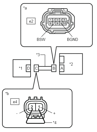
*1 Front Seat Inner Belt Assembly RH *2 Occupant Detection ECU *3 Front Seat Wire RH *4 Service Wire *a Front view of wire harness connector
(to Occupant Detection ECU)*b Front view of wire harness connector
(to Front Seat Inner Belt Assembly RH) - Turn the ignition switch to ON.
- Measure the voltage according to the value(s) in the table below.
Standard Voltage
Tester Connection Condition Specified Condition e2-7 (BSW) - Body ground Ignition switch ON Below 1 V e2-9 (BGND) - Body ground Ignition switch ON Below 1 V - Turn the ignition switch off.
- Disconnect the cable from the negative (-) auxiliary battery terminal.
- Using a service wire, connect terminals 1 (+) and 2 (-) of connector C.NOTE:
Do not forcibly insert the service wire into the terminals of the connector when connecting the wire.
- Measure the resistance according to the value(s) in the table below.
Standard Resistance
Tester Connection Condition Specified Condition e2-7 (BSW) - e2-9 (BGND) Always Below 1 Ω - Disconnect the service wire from connector C.
- Measure the resistance according to the value(s) in the table below.
Standard Resistance
Tester Connection Condition Specified Condition e2-7 (BSW) - e2-9 (BGND) Always 1 MΩ or higher e2-7 (BSW) - Body ground Always 1 MΩ or higher e2-9 (BGND) - Body ground Always 1 MΩ or higher Result
Proceed to OK NG
Result:
NG
REPLACE FRONT SEAT WIRE RH
Result:
OK
See step 3
- Connect the cable to the negative (-) auxiliary battery terminal.
- CHECK DTC
- Connect the connectors to the occupant detection ECU and front seat inner belt assembly RH.
- Connect the cable to the negative (-) auxiliary battery terminal.
- Turn the ignition switch to ON, and wait for at least 60 seconds.
- Clear the DTCs stored in the occupant detection ECU.
Body Electrical > Occupant Detection > Clear DTCs
- Clear the DTCs stored in the airbag sensor assembly.
Body Electrical > SRS Airbag > Clear DTCs
- Turn the ignition switch off.
- Turn the ignition switch to ON, and wait for at least 10 seconds.
- Check for DTCs.
Body Electrical > Occupant Detection > Trouble Codes
OK
DTC B1771 is not output.
HINT:
Codes other than DTC B1771 may be output at this time, but they are not related to this check.
- Turn the ignition switch off.
Result
Proceed to OK NG
Result:
OK
USE SIMULATION METHOD TO CHECK. Refer to HOW TO PROCEED WITH TROUBLESHOOTING [12/2019 - ]
Result:
NG
See step 4
- CHECK FRONT SEAT INNER BELT ASSEMBLY RH
- Disconnect the cable from the negative (-) auxiliary battery terminal.
- Replace the front seat inner belt assembly RH with a known good one.
for Manual Seat: Refer to REMOVAL [12/2019 - 10/2022]
for Power Seat: Refer to REMOVAL [12/2019 - 10/2022]
HINT:
Perform the following inspection using known good parts from another vehicle if possible.
- Connect the cable to the negative (-) auxiliary battery terminal.
- Turn the ignition switch to ON, and wait for at least 60 seconds.
- Clear the DTCs stored in the occupant detection ECU.
Body Electrical > Occupant Detection > Clear DTCs
- Clear the DTCs stored in the airbag sensor assembly.
Body Electrical > SRS Airbag > Clear DTCs
- Turn the ignition switch off.
- Turn the ignition switch to ON, and wait for at least 10 seconds.
- Check for DTCs.
Body Electrical > Occupant Detection > Trouble Codes
OK
DTC B1771 is not output.
HINT:
Codes other than DTC B1771 may be output at this time, but they are not related to this check.
- Turn the ignition switch off.
- Disconnect the cable from the negative (-) auxiliary battery terminal.
- Restore the front seat inner belt assembly RH that was installed for testing to its original location.
for Manual Seat: Refer to REMOVAL [12/2019 - 10/2022]
for Power Seat: Refer to REMOVAL [12/2019 - 10/2022]
Result
Proceed to OK NG
Result:
OK
REPLACE FRONT SEAT INNER BELT ASSEMBLY RH
for Manual Seat: Refer to REMOVAL [12/2019 - 10/2022]
for Power Seat: Refer to REMOVAL [12/2019 - 10/2022]
Result:
NG
See step 5
- REPLACE OCCUPANT DETECTION ECU
- Turn the ignition switch off.
- Disconnect the cable from the negative (-) auxiliary battery terminal.
- Replace the occupant detection ECU with a new one.
Refer to REMOVAL [12/2019 - 10/2022]
- Connect the cable to the negative (-) auxiliary battery terminal.
Result
Proceed to NEXT
Result:
NEXT
See step 6
- PERFORM ZERO POINT CALIBRATION
- Using the GTS, perform Zero Point Calibration.
Refer to INITIALIZATION [12/2019 - 10/2021]
Result
Proceed to NEXT
Result:
NEXT
END
- Using the GTS, perform Zero Point Calibration.