Terminals Of Ecu [12/2019 - 11/2023]
- HYBRID VEHICLE CONTROL ECU
Terminal No.
(Symbol)Terminal Description Condition Specified Condition A31-2 (R) - H67-3 (E1) Shift lever position signal Ignition switch ON, shift lever in R 6.0 to 14 V Ignition switch ON, shift lever not in R 0 to 1.5 V A31-3 (DB1) - H67-3 (E1) Shift lever position signal Ignition switch ON, shift lever in D or S 6.0 to 14 V Ignition switch ON, shift lever not in D or S 0 to 1.5 V A31-4 (HMCH) - H67-3 (E1) Communication signal Ignition switch ON Pulse generation
(Waveform 1)A31-5 (MREL) - H67-3 (E1) Main relay Ignition switch ON 11 to 14 V A31-6 (HSDN) - H67-3 (E1) MG ECU shutdown signal Ignition switch ON (READY) 0 to 1.5 V A31-7 (STP) - H67-3 (E1) Stop light switch Brake pedal depressed 11 to 14 V Brake pedal released 0 to 1.5 V A31-8 (LIN3) - H67-3 (E1) LIN communication signal
(A/C inverter, battery state sensor)Ignition switch ON (READY) Pulse generation A31-11 (+B1) - H67-3 (E1) Power source Ignition switch ON 11 to 14 V A31-12 (OPM2) - H67-3 (E1) OIL PMP relay Ignition switch ON (READY), engine stopped 11 to 14 V A31-14 (HMCL) - H67-3 (E1) Communication signal Ignition switch ON Pulse generation
(Waveform 1)A31-15 (DB2) - H67-3 (E1) Shift lever position signal Ignition switch ON, shift lever in D or S 6.0 to 14 V Ignition switch ON, shift lever not in D or S 0 to 1.5 V A31-16 (PR) - H67-3 (E1) Shift lever position signal Ignition switch ON, shift lever in P or R 6.0 to 14 V Ignition switch ON, shift lever not in P or R 0 to 1.5 V A31-18 (PSFT) - H67-3 (E1) Shift lever position sensor power source Ignition switch ON (ACC) 6.0 to 14 V A31-20 (BL) - H67-3 (E1) Back-up light relay Ignition switch ON, shift lever in R 11 to 14 V A31-21 (OPM1) - H67-3 (E1) Oil pump with motor assembly signal Ignition switch ON (READY), engine stopped Pulse generation
(Waveform 2)A31-22 (NOPM) - H67-3 (E1) Oil pump with motor assembly signal Ignition switch ON (READY), engine stopped Pulse generation
(Waveform 2)A31-24 (VCPA) - A31-37 (EPA) Accelerator pedal sensor assembly power source (for VPA) Ignition switch ON 4.5 to 5.5 V A31-26 (VCP2) - A31-25 (EPA2) Accelerator pedal sensor assembly power source (for VPA2) Ignition switch ON 4.5 to 5.5 V A31-28 (P) - H67-3 (E1) Shift lever position signal Ignition switch ON, shift lever in P 6.0 to 14 V Ignition switch ON, shift lever not in P 0 to 1.5 V A31-29 (N) - H67-3 (E1) Shift lever position signal Ignition switch ON, shift lever in N 6.0 to 14 V Ignition switch ON, shift lever not in N 0 to 1.5 V A31-30 (PNB) - H67-3 (E1) Shift lever position signal Ignition switch ON, shift lever in P or N 6.0 to 14 V A31-33 (NIWP) - H67-3 (E1) Inverter water pump assembly signal Ignition switch ON (READY) Pulse generation
(Waveform 3)A31-34 (IWP) - H67-3 (E1) Inverter water pump assembly signal Ignition switch ON (READY) Pulse generation
(Waveform 3)A31-36 (VPA) - A31-37 (EPA) Accelerator pedal sensor assembly (for accelerator pedal position detection) Ignition switch ON, accelerator pedal released 0.4 to 1.4 V Ignition switch ON, engine stopped, shift lever in P, accelerator pedal fully depressed 2.6 to 4.5 V A31-38 (VPA2) - A31-25 (EPA2) Accelerator pedal sensor assembly (for accelerator pedal sensor malfunction detection) Ignition switch ON, accelerator pedal released 1.0 to 2.2 V Ignition switch ON, engine stopped, shift lever in P, accelerator pedal fully depressed 3.4 to 5.3 V A31-40 (TTA) - A31-39 (ETTA) Transmission fluid temperature sensor Ignition switch ON, temperature 25°C (77°F) 3.6 to 4.6 V Ignition switch ON, temperature 60°C (140°F) 2.2 to 3.2 V A31-46 (MMT) - A31-45 (MMTG) Motor temperature sensor Ignition switch ON, temperature 25°C (77°F) 3.6 to 4.6 V Ignition switch ON, temperature 60°C (140°F) 2.2 to 3.2 V A31-48 (GMT) - A31-47 (GMTG) Generator temperature sensor Ignition switch ON, temperature 25°C (77°F) 3.6 to 4.6 V Ignition switch ON, temperature 60°C (140°F) 2.2 to 3.2 V A32-5 (ILK) - H67-3 (E1) Interlock switch Ignition switch ON, service plug grip installed correctly 0 to 1.5 V Ignition switch ON, service plug grip not installed 11 to 14 V A32-7 (CA3P) - H67-3 (E1) CAN communication signal Ignition switch ON Pulse generation
(Waveform 4)A32-8 (CA1L) - H67-3 (E1) CAN communication signal Ignition switch ON Pulse generation
(Waveform 5)A32-9 (CA4H) - H67-3 (E1) CAN communication signal Ignition switch ON Pulse generation
(Waveform 6)A32-13 (SMRG) - A32-12 (E01) System main relay operation signal Ignition switch ON → Ignition switch ON (READY) Pulse generation
(Waveform 7)A32-15 (SMRP) - A32-12 (E01) System main relay operation signal Ignition switch ON → Ignition switch ON (READY) Pulse generation
(Waveform 7)A32-16 (SMRB) - A32-12 (E01) System main relay operation signal Ignition switch ON → Ignition switch ON (READY) Pulse generation
(Waveform 7)A32-20 (CA3N) - H67-3 (E1) CAN communication signal Ignition switch ON Pulse generation
(Waveform 4)A32-21 (CA1H) - H67-3 (E1) CAN communication signal Ignition switch ON Pulse generation
(Waveform 5)A32-22 (CA4L) - H67-3 (E1) CAN communication signal Ignition switch ON Pulse generation
(Waveform 6)A32-25 (PLKC) - H67-3 (E1) Shift lock release request signal Ignition switch ON (READY), brake pedal depressed 11 to 14 V Ignition switch ON (READY), brake pedal released 0 to 1.5 V A32-28 (ST1-) - H67-3 (E1) Stop light switch signal Ignition switch ON, brake pedal depressed 0 to 1.5 V Ignition switch ON, brake pedal released 11 to 14 V A32-29 (ACCI) - H67-3 (E1) ACC relay Ignition switch ON (ACC) 11 to 14 V A32-35 (IG2) - H67-3 (E1) Power source Ignition switch ON 11 to 14 V H67-1 (+B2) - H67-3 (E1) Power source Ignition switch ON 11 to 14 V H67-4 (ST2) - H67-3 (E1) Starter signal Ignition switch ON 0 to 1.5 V H67-7 (INDR) - H67-3 (E1) Shift position indicator signal Ignition switch ON, shift lever in R 0 to 3.2 V Ignition switch ON, shift lever not in R 11 to 14 V H67-8 (INDD) - H67-3 (E1) Shift position indicator signal Ignition switch ON, shift lever in D 0 to 3.2 V Ignition switch ON, shift lever not in D 11 to 14 V H67-11 (SFTD) - H67-3 (E1) Transmission control Ignition switch ON, shift lever in S 11 to 14 V Ignition switch ON, shift lever in (-) 0 to 1.5 V H67-19 (INDP) - H67-3 (E1) Shift position indicator signal Ignition switch ON, shift lever in P 0 to 3.2 V Ignition switch ON, shift lever not in P 11 to 14 V H67-20 (INDM) - H67-3 (E1) Shift position indicator signal Ignition switch ON, shift lever in S 0 to 3.2 V Ignition switch ON, shift lever not in S 11 to 14 V H67-21 (INDN) - H67-3 (E1) Shift position indicator signal Ignition switch ON, shift lever in N 0 to 3.2 V Ignition switch ON, shift lever not in N 11 to 14 V H67-24 (SFTU) - H67-3 (E1) Transmission control Ignition switch ON, shift lever in S 11 to 14 V Ignition switch ON, shift lever in (+) 0 to 1.5 V H67-25 (M) - H67-3 (E1) Transmission control Ignition switch ON, shift lever in S 11 to 14 V Ignition switch ON, shift lever not in S 0 to 1.5 V H67-27 (BATT) - H67-3 (E1) Constant power source Ignition switch ON 11 to 14 V Ignition switch ON (READY) 11 to 15.5 V H67-33 (EVSW) - H67-3 (E1) EV drive mode switch (pattern select switch assembly) Ignition switch ON, EV drive mode switch (pattern select switch assembly) not operated 11 to 14 V Ignition switch ON, EV drive mode switch (pattern select switch assembly) being pushed and held 0 to 1.5 V H67-35 (HCIV)*1 - H67-3 (E1) AC120 V main switch (main switch assembly) signal Ignition switch ON, AC120 V main switch (main switch assembly) not operated 11 to 14 V Ignition switch ON, AC120 V main switch (main switch assembly) being pushed and held 0 to 1.5 V H67-37 (DMS-) - H67-3 (E1) Drive mode select switch (No. 1 pattern select switch assembly) signal Ignition switch ON, Drive mode select switch (No. 1 pattern select switch assembly) not turned 11 to 14 V Ignition switch ON, Drive mode select switch (No. 1 pattern select switch assembly) backward and held 0 to 1.5 V H67-38 (DMS+) - H67-3 (E1) Drive mode select switch (No. 1 pattern select switch assembly) signal Ignition switch ON, Drive mode select switch (No. 1 pattern select switch assembly) not turned 11 to 14 V Ignition switch ON, Drive mode select switch (No. 1 pattern select switch assembly) forward and held 0 to 1.5 V H67-40 (NOAC)*1 - H67-3 (E1) AC120 V inverter prohibition request signal Ignition switch ON (READY), Voltage inverter operation permission signal being received 5.2 to 10.3 V Ignition switch ON (READY), Voltage inverter operation prohibition signal being received 0.1 to 0.5 V H67-44 (IGB) - H67-3 (E1) Power source Ignition switch ON 11 to 14 V - *1: w/ 1500W Voltage Inverter
- Oscilloscope waveforms
HINT:
Oscilloscope waveform samples are provided here for informational purposes. Noise and fluttering waveforms have been omitted.
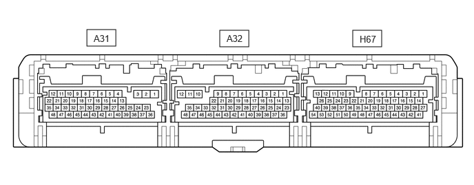
- Waveform 1 (Communication signal)
Item Content Terminal CH1: A31-4 (HMCH) - H67-3 (E1)
CH2: A31-14 (HMCL) - H67-3 (E1)Equipment Setting 1 V/DIV., 50 μs./DIV. Condition Ignition switch ON HINT:
The waveform will vary depending on the content of the digital communication (digital signal).
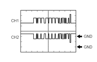
- Waveform 2 (Oil pump with motor assembly signal)
Item Content Terminal CH1: A31-21 (OPM1) - H67-3 (E1)
CH2: A31-22 (NOPM) - H67-3 (E1)Equipment Setting 10 V/DIV., 20 ms./DIV. Condition Ignition switch ON (READY), engine stopped HINT:
The wavelength will vary with the operating speed of the oil pump.
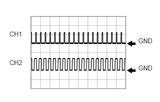
- Waveform 3 (Inverter water pump assembly signal)
Item Content Terminal CH1: A31-34 (IWP) - H67-3 (E1)
CH2: A31-33 (NIWP) - H67-3 (E1)Equipment Setting 5 V/DIV., 20 ms./DIV. Condition Ignition switch ON (READY) HINT:
The duty of the IWP signal and the frequency of the NIWP signal change according to the coolant (for inverter) temperature.
- Waveform 4 (CAN communication signal)
Item Content Terminal CH1: A32-7 (CA3P) - H67-3 (E1)
CH2: A32-20 (CA3N) - H67-3 (E1)Equipment Setting 1 V/DIV., 50 μs./DIV. Condition Ignition switch ON HINT:
The waveform will vary depending on the content of the digital communication (digital signal).
- Waveform 5 (CAN communication signal)
Item Content Terminal CH1: A32-21 (CA1H) - H67-3 (E1)
CH2: A32-8 (CA1L) - H67-3 (E1)Equipment Setting 1 V/DIV., 50 μs./DIV. Condition Ignition switch ON HINT:
The waveform will vary depending on the content of the digital communication (digital signal).
- Waveform 6 (CAN Communication signal)
Item Content Terminal CH1: A32-9 (CA4H) - H67-3 (E1)
CH2: A32-22 (CA4L) - H67-3 (E1)Equipment Setting 1 V/DIV., 50 μs./DIV. Condition Ignition switch ON HINT:
The waveform will vary depending on the content of the digital communication (digital signal).
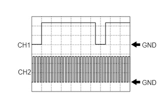
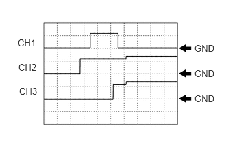
- Waveform 7 (System main relay operation signal)
Item Content Terminal CH1: A32-15 (SMRP) - A32-12 (E01)
CH2: A32-16 (SMRB) - A32-12 (E01)
CH3: A32-13 (SMRG) - A32-12 (E01)Equipment Setting 10 V/DIV., 200 ms./DIV. Condition Ignition switch ON → Ignition switch ON (READY)
- Waveform 1 (Communication signal)
- BATTERY VOLTAGE SENSOR
Terminal No.
(Symbol)Terminal Description Condition Specified Condition z12-1 (TC0) - z12-13 (GC0) HV battery intake air temperature sensor Ignition switch ON, HV battery intake air temperature: -40 to 90°C (-40 to 194°F) 4.8 (-40°C (-40°F)) to 1.0 V (90°C (194°F)) z12-2 (TB5) - z12-14 (GB5) Battery temperature sensor 5 Ignition switch ON, HV battery temperature: -40 to 90°C (-40 to 194°F) 4.8 (-40°C (-40°F)) to 1.0 V (90°C (194°F)) z12-3 (TB4) - z12-15 (GB4) Battery temperature sensor 4 Ignition switch ON, HV battery temperature: -40 to 90°C (-40 to 194°F) 4.8 (-40°C (-40°F)) to 1.0 V (90°C (194°F)) z12-4 (TB3) - z12-16 (GB3) Battery temperature sensor 3 Ignition switch ON, HV battery temperature: -40 to 90°C (-40 to 194°F) 4.8 (-40°C (-40°F)) to 1.0 V (90°C (194°F)) z12-5 (TB2) - z12-17 (GB2) Battery temperature sensor 2 Ignition switch ON, HV battery temperature: -40 to 90°C (-40 to 194°F) 4.8 (-40°C (-40°F)) to 1.0 V (90°C (194°F)) z12-6 (TB1) - z12-18 (GB1) Battery temperature sensor 1 Ignition switch ON, HV battery temperature: -40 to 90°C (-40 to 194°F) 4.8 (-40°C (-40°F)) to 1.0 V (90°C (194°F)) z12-7 (TB0) - z12-19 (GB0) Battery temperature sensor 0 Ignition switch ON, HV battery temperature: -40 to 90°C (-40 to 194°F) 4.8 (-40°C (-40°F)) to 1.0 V (90°C (194°F)) z12-9 (IB0) - z12-22 (GIB) Battery current sensor Ignition switch ON 0.5 to 4.5 V z12-10 (VIB) - z12-22 (GIB) Power source for battery current sensor Ignition switch ON 4.5 to 5.5 V y1-1 (IGCT) - y1-7 (GND) Control signal Ignition switch ON 11 to 14 V y1-2 (CA1H) - y1-7 (GND) CAN communication signal Ignition switch ON Pulse generation
(waveform 1)y1-3 (CA1L) - y1-7 (GND) CAN communication signal Ignition switch ON Pulse generation
(waveform 1)y1-5 (SI0) - y1-7 (GND) Battery cooling blower (No. 0) operation signal Cooling blower operating Pulse generation
(Waveform 2)Cooling blower not operating 4.5 to 5.5 V y1-6 (SI1) - y1-7 (GND) Battery cooling blower (No. 1) operation signal Cooling blower operating Pulse generation
(Waveform 3)Cooling blower not operating 4.5 to 5.5 V y1-7 (GND) - Body ground Ground Always (continuity check) Below 1 Ω y1-11 (FP0) - y1-7 (GND) Battery cooling blower (No. 0) monitor signal Cooling blower not operating 0 Hz Cooling blower operating Pulse generation
(waveform 4)y1-12 (FP1) - y1-7 (GND) Battery cooling blower (No. 1) monitor signal Cooling blower not operating 0 Hz Cooling blower operating Pulse generation
(waveform 5)- Oscilloscope waveforms
HINT:
Oscilloscope waveform samples are provided here for informational purposes. Noise and fluttering waveforms have been omitted.
- Waveform 1 CAN communication signal)
Item Content Terminal CH1: y1-2 (CA1H) - y1-7 (GND)
CH2: y1-3 (CA1L) - y1-7 (GND)Equipment Setting 1 V/DIV., 50 μs./DIV. Condition Ignition switch ON HINT:
The waveform will vary depending on the content of the digital communication (digital signal).
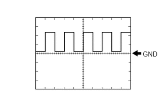
- Waveform 2 (Battery cooling blower (No. 0) operation signal)
Item Content Terminal y1-5 (SI0) - y1-7 (GND) Equipment Setting 10 V/DIV., 1 ms./DIV. Condition Battery cooling blower assembly operating (Active Test of cooling fan being performed) HINT:
The waveform will vary with the operating speed of the battery cooling blower assembly.
- Waveform 3 (Battery cooling blower (No. 1) operation signal)
Item Content Terminal y1-6 (SI1) - y1-7 (GND) Equipment Setting 10 V/DIV., 1 ms./DIV. Condition Battery cooling blower assembly operating (Active Test of cooling fan being performed) HINT:
The waveform will vary with the operating speed of the battery cooling blower assembly.
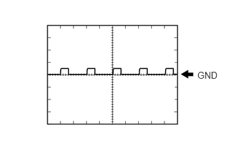
- Waveform 4 (Battery cooling blower (No. 0) monitor signal)
Item Content Terminal y1-11 (FP0) - y1-7 (GND) Equipment Setting 2 V/DIV., 2 ms/DIV. Condition Battery cooling blower assembly operating (Active Test of cooling fan being performed) HINT:
The frequency of the waveform will vary with the operating speed of the battery cooling blower assembly.
- Waveform 5 (Battery cooling blower (No. 1) monitor signal)
Item Content Terminal y1-12 (FP1) - y1-7 (GND) Equipment Setting 2 V/DIV., 2 ms/DIV. Condition Battery cooling blower assembly operating (Active Test of cooling fan being performed) HINT:
The frequency of the waveform will vary with the operating speed of the battery cooling blower assembly.
- Waveform 1 CAN communication signal)
- Oscilloscope waveforms