Diagnosis System [12/2019 - 11/2023]
- DESCRIPTION
- The hybrid vehicle control ECU has a self-diagnosis system. If the computer, Hybrid Control System, or a component is not working properly, the ECU records the conditions that relate to the fault. The ECU also illuminates the master warning in the combination meter assembly and provides other appropriate messages on the multi-information display, such as the HV system warning message, HV battery warning message, or discharge warning message.
- When troubleshooting OBD II (On-Board Diagnostics) vehicles, the GTS (complying with SAE J1978) must be connected to the DLC3 (Data Link Connector 3) of the vehicle. Various data in the vehicle motor generator control ECU can then be read.
- OBD II regulations require that the vehicle's on-board computer illuminates the MIL (Malfunction Indicator Lamp) on the instrument panel when the computer detects a malfunction in:
- The emission control system components.
- The powertrain control components (which affect vehicle emissions).
- The computer itself.
In addition, the applicable DTCs prescribed by SAE J2012 are recorded in the motor generator control ECU memory. If the malfunction does not recur in 3 consecutive trips, the MIL turns off automatically but the DTCs remain recorded in the motor generator control ECU memory.
- To check for DTCs, connect the GTS to the DLC3. The GTS displays DTCs, Freeze Frame Data, and a variety of Hybrid Control System data. The DTCs and Freeze Frame Data can be cleared with the GTS. In order to enhance the OBD function on vehicles and develop the off-board diagnosis system, Controller Area Network (CAN) communication is used in this system. CAN is a network which uses a pair of data transmission lines spanning multiple computers and sensors. It allows for high speed communications between the systems and simplification of the wire harness connections.
- The hybrid vehicle control ECU has a self-diagnosis system. If the computer, Hybrid Control System, or a component is not working properly, the ECU records the conditions that relate to the fault. The ECU also illuminates the master warning in the combination meter assembly and provides other appropriate messages on the multi-information display, such as the HV system warning message, HV battery warning message, or discharge warning message.
- 2 TRIP DETECTION LOGIC
Following is the description for storage of DTC using "2 trip detection logic".
- When a malfunction is first detected, the malfunction is temporarily stored in the hybrid vehicle control ECU memory (1st trip). If the same malfunction is detected during the next drive cycle, the MIL is illuminated (2nd trip).
- FREEZE FRAME DATA
- The hybrid vehicle control ECU records vehicle and driving condition information as Freeze Frame Data the moment a DTC is stored. When troubleshooting, Freeze Frame Data can be helpful in determining whether the vehicle was moving or stationary, whether the engine was warmed up or not, as well as other data recorded at the time of a malfunction.
- AUXILIARY BATTERY VOLTAGE
Standard Voltage
Switch Condition Specified Condition Ignition switch ON 11 to 14 V - If voltage is below 11 V, recharge or replace the auxiliary battery.NOTE:
After turning the ignition switch off, waiting time may be required before disconnecting the cable from the negative (-) auxiliary battery terminal. Therefore, make sure to read the disconnecting the cable from the negative (-) auxiliary battery terminal notices before proceeding with work.
Refer to INITIALIZATION [12/2019 - 09/2020] , or refer to INITIALIZATION [09/2020 - 10/2021] , or refer to INITIALIZATION [10/2021 - 10/2022] , or refer to INITIALIZATION [10/2022 - 11/2023]
- If voltage is below 11 V, recharge or replace the auxiliary battery.
- MIL (Malfunction Indicator Lamp)
- The MIL is illuminated when the ignition switch is first turned to ON, before the READY light comes on.
- When the READY indicator turns on, the MIL should turn off. If the MIL remains illuminated, the diagnosis system has detected a malfunction or abnormality in the system.
HINT:
If the MIL is not illuminated when the ignition switch is first turned to ON, check the MIL circuit.
for SFI System: Refer to MIL Circuit [12/2019 - 10/2022] , or refer to MIL Circuit [10/2022 - 11/2023]
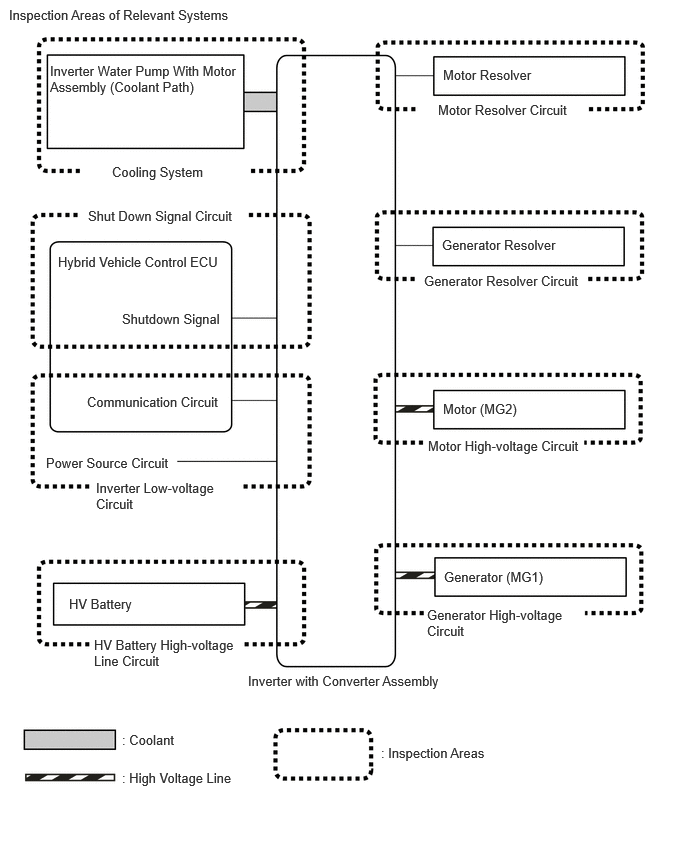
- RELEVANT SYSTEMS CHECK
The inspection areas and outline of the inspection for each circuit are listed below.
INSPECTION DETAILS OF RELEVANT SYSTEMSSystem to be Inspected Malfunction Possibility Inspection Content Motor Resolver Circuit Motor resolver signal - Open or short circuit in the motor resolver, connectors or cables
Motor High-voltage Circuit Motor (MG2) output - Open or short circuit in the motor (MG2), connectors or cables
Generator Resolver Circuit Generator resolver signal - Open or short circuit in the generator resolver, connectors or cables
Generator High-voltage Circuit Generator (MG1) output - Open or short circuit in the generator (MG1), connectors or cables
Inverter Low-voltage Circuit Power supply voltage from +B or communication between hybrid vehicle control ECU and motor generator control ECU - Open or short circuit in communication line between hybrid vehicle control ECU and motor generator control ECU
- Open or short circuit in the +B or ground lines
- Fuse is blown
HV Battery High-voltage Line Circuit High voltage power supply from HV battery - Open or short circuit in the system main relay, connectors or cables
Cooling System Temperature abnormally high - Grille blockage
- Whether coolant is present
- Whether there is a possibility that coolant was frozen when malfunction occurs
- Cooling hose blockage
- HV radiator fan operation
Shutdown Signal Circuit Shutdown signal - Open or short circuit in shutdown signal communication line between hybrid vehicle control ECU and motor generator ECU
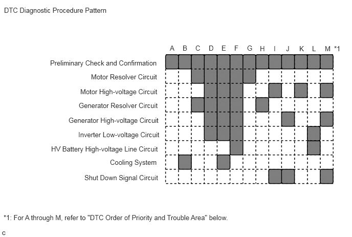
- DTC PRIORITY LEVEL AND TROUBLE AREAS
- Each DTC diagnostic procedure for the hybrid control system consists of a combination of the various relevant system (circuit) inspections.
- When multiple DTCs are output, performing each diagnostic procedure in order of priority can lead to a more accurate diagnosis.
INSPECTION DETAILS OF RELEVANT SYSTEMSDTC No. Detection Item Order of Priority Inspection Pattern 1 2 3 4 5 Microcomputer Malfunction Power Source Circuit Malfunction Communication System Malfunction Sensor and Actuator Circuit Malfunction System Malfunction P0560-14 System Voltage (BATT) Circuit Short to Ground or Open - ◦ - - - - P0606-47 Hybrid/EV Powertrain Control Module Processor Watchdog / Safety MCU Failure ◦ - - - - - P0606-87 Hybrid/EV Powertrain Control Module Processor to Monitoring Processor Missing Message ◦ - - - - - P0606-94 Hybrid/EV Powertrain Control Module Processor Unexpected Operation ◦ - - - - - P060A-29 Hybrid/EV Powertrain Control Module Monitoring Processor Signal Invalid ◦ - - - - - P060A-44 Hybrid/EV Powertrain Control Module Monitoring Processor Data Memory Failure ◦ - - - - - P060A-45 Hybrid/EV Powertrain Control Module Monitoring Processor Program Memory Failure ◦ - - - - - P060A-47 Hybrid/EV Powertrain Control Module Monitoring Processor Watchdog / Safety MCU Failure ◦ - - - - - P060A-49 Hybrid/EV Powertrain Control Module Monitoring Processor Internal Electronic Failure ◦ - - - - - P060A-87 Hybrid/EV Powertrain Control Module Processor from Monitoring Processor Missing Message ◦ - - - - - P060A-94 Hybrid/EV Powertrain Control Module Monitoring Processor Unexpected Operation ◦ - - - - - P060B-1C Hybrid/EV Powertrain Control Module A/D Processing Voltage Out of Range ◦ - - - - - P060B-49 Hybrid/EV Powertrain Control Module A/D Processing Internal Electronic Failure ◦ - - - - - P060B-71 Hybrid/EV Powertrain Control Module A/D Processing Actuator Stuck ◦ - - - - - P062F-44 Hybrid/EV Powertrain Control Module EEPROM Data Memory Failure ◦ - - - - - P062F-46 Hybrid/EV Powertrain Control Module EEPROM Calibration / Parameter Memory Failure ◦ - - - - - P0688-1F ECM/PCM Power Relay Sense Circuit Intermittent - ◦ - - - - P0705-62 Transmission Range Sensor "A" Circuit (PRNDL Input) Signal Compare Failure - - - ◦ - - P0A0A-13 High Voltage System Interlock Circuit Open - - - - ◦ - P0A0A-92 High Voltage System Interlock Performance or Incorrect Operation - - - - ◦ - P0A1B-49 Drive Motor "A" Control Module Internal Electronic Failure ◦ - - - - - P0A1B-94 Drive Motor "A" Control Module Unexpected Operation ◦ - - - - - P0A2A-11 Drive Motor "A" Temperature Sensor Circuit Short to Ground - - - ◦ - - P0A2A-15 Drive Motor "A" Temperature Sensor Circuit Short to Auxiliary Battery or Open - - - ◦ - - P0A2A-1C Drive Motor "A" Temperature Sensor Voltage Out of Range - - - ◦ - - P0A2A-1F Drive Motor "A" Temperature Sensor Circuit Intermittent - - - ◦ - - P0A36-11 Generator Temperature Sensor Circuit Short to Ground - - - ◦ - - P0A36-15 Generator Temperature Sensor Circuit Short to Auxiliary Battery or Open - - - ◦ - - P0A36-1C Generator Temperature Sensor Voltage Out of Range - - - ◦ - - P0A36-1F Generator Temperature Sensor Circuit Intermittent - - - ◦ - - P0A81-00 Hybrid/EV Battery Cooling Fan 1 Control Circuit High - - - ◦ - - P0A81-11 Hybrid/EV Battery Cooling Fan 1 Circuit Short to Ground - - - ◦ - - P0A81-15 Hybrid/EV Battery Cooling Fan 1 Circuit Short to Auxiliary Battery or Open - - - ◦ - - P0A81-4B Hybrid/EV Battery Cooling Fan 1 Over Temperature - - - ◦ - - P0A81-96 Hybrid/EV Battery Cooling Fan 1 Component Internal Failure - - - ◦ - - P0A81-98 Hybrid/EV Battery Cooling Fan 1 Component or System Over Temperature - - - ◦ - - P0A93-00 Inverter "A" Cooling System Performance - - - - ◦ B P0A95-63 High Voltage Fuse Accumulated Load History - - - - ◦ - P0A96-00 Hybrid/EV Battery Cooling Fan 2 Control Circuit High - - - ◦ - - P0A96-11 Hybrid/EV Battery Cooling Fan 2 Circuit Short to Ground - - - ◦ - - P0A96-15 Hybrid/EV Battery Cooling Fan 2 Circuit Short to Auxiliary Battery or Open - - - ◦ - - P0A96-4B Hybrid/EV Battery Cooling Fan 2 Over Temperature - - - ◦ - - P0A96-96 Hybrid/EV Battery Cooling Fan 2 Component Internal Failure - - - ◦ - - P0A96-98 Hybrid/EV Battery Cooling Fan 2 Component or System Over Temperature - - - ◦ - - P0A9B-11 Hybrid/EV Battery Temperature Sensor "A" Circuit Short to Ground - - - - ◦ - P0A9B-15 Hybrid/EV Battery Temperature Sensor "A" Circuit Short to Auxiliary Battery or Open - - - ◦ - - P0A9B-1C Hybrid/EV Battery Temperature Sensor "A" Voltage Out of Range - - - ◦ - - P0A9B-2A Hybrid/EV Battery Temperature Sensor "A" Signal Stuck In Range - - - ◦ - - P0AA0-00 Hybrid/EV Battery Positive Contactor Circuit Stuck Closed - - - - ◦ - P0AA0-73 Hybrid/EV Battery Positive and Negative Contactor Actuator Stuck Closed - - - - ◦ - P0AA3-73 Hybrid/EV Battery Negative Contactor Actuator Stuck Closed - - - - ◦ - P0AA6-49 Hybrid/EV Battery Voltage System Isolation Internal Electronic Failure - - - - ◦ - P0AA7-49 Hybrid/EV Battery Voltage Isolation Sensor Circuit Internal Electronic Failure - - - ◦ - - P0AAC-11 Hybrid/EV Battery Air Temperature Sensor "A" Circuit Short to Ground - - - ◦ - - P0AAC-15 Hybrid/EV Battery Air Temperature Sensor "A" Circuit Short to Auxiliary Battery or Open - - - ◦ - - P0ABF-00 Hybrid/EV Battery Current Sensor "A" Circuit Range/Performance - - - ◦ - - P0ABF-11 Hybrid/EV Battery Current Sensor "A" Circuit Short to Ground - - - ◦ - - P0ABF-15 Hybrid/EV Battery Current Sensor "A" Circuit Short to Auxiliary Battery or Open - - - ◦ - - P0ABF-28 Hybrid/EV Battery Current Sensor "A" Signal Bias Level Out of Range / Zero Adjustment Failure - - - ◦ - - P0ABF-2A Hybrid/EV Battery Current Sensor "A" Signal Stuck In Range - - - ◦ - - P0AC5-11 Hybrid/EV Battery Temperature Sensor "B" Circuit Short to Ground - - - ◦ - - P0AC5-15 Hybrid/EV Battery Temperature Sensor "B" Circuit Short to Auxiliary Battery or Open - - - ◦ - - P0AC5-1C Hybrid/EV Battery Temperature Sensor "B" Voltage Out of Range - - - ◦ - - P0AC5-2A Hybrid/EV Battery Temperature Sensor "B" Signal Stuck In Range - - - ◦ - - P0ACA-11 Hybrid/EV Battery Temperature Sensor "C" Circuit Short to Ground - - - ◦ - - P0ACA-15 Hybrid/EV Battery Temperature Sensor "C" Circuit Short to Auxiliary Battery or Open - - - ◦ - - P0ACA-1C Hybrid/EV Battery Temperature Sensor "C" Voltage Out of Range - - - ◦ - - P0ACA-2A Hybrid/EV Battery Temperature Sensor "C" Signal Stuck In Range - - - ◦ - - P0AD9-11 Hybrid/EV Battery Positive Contactor Circuit Short to Ground - - - ◦ - - P0AD9-15 Hybrid/EV Battery Positive Contactor Circuit Short to Auxiliary Battery or Open - - - ◦ - - P0ADD-11 Hybrid/EV Battery Negative Contactor Circuit Short to Ground - - - ◦ - - P0ADD-15 Hybrid/EV Battery Negative Contactor Circuit Short to Auxiliary Battery or Open - - - ◦ - - P0AE1-73 Hybrid/EV Battery Precharge Contactor Actuator Stuck Closed - - - - ◦ - P0AE4-11 Hybrid/EV Battery Precharge Contactor Circuit Short to Ground - - - ◦ - - P0AE4-15 Hybrid/EV Battery Precharge Contactor Circuit Short to Auxiliary Battery or Open - - - ◦ - - P0AE8-11 Hybrid/EV Battery Temperature Sensor "D" Circuit Short to Ground - - - ◦ - - P0AE8-15 Hybrid/EV Battery Temperature Sensor "D" Circuit Short to Auxiliary Battery or Open - - - ◦ - - P0AE8-1C Hybrid/EV Battery Temperature Sensor "D" Voltage Out of Range - - - ◦ - - P0AE8-2A Hybrid/EV Battery Temperature Sensor "D" Signal Stuck In Range - - - ◦ - - P0AFC-00 Hybrid/EV Battery Sensor Module ◦ - - - - - P0AFC-16 Hybrid/EV Battery Sensor Module Circuit Voltage Below Threshold - ◦ - - - - P0AFC-49 Hybrid/EV Battery Sensor Module Internal Electronic Failure ◦ - - - - - P0AFC-62 Hybrid/EV Battery Sensor Module Signal Compare Failure ◦ - - - - - P0AFC-96 Hybrid/EV Battery Sensor Module Component Internal Failure ◦ - - - - - P0B23-1C Hybrid/EV Battery "A" Voltage Sensor Voltage Out of Range - - - ◦ - - P0B3B-14 Hybrid/EV Battery Voltage Sensor "A" Circuit Short to Ground or Open - - - ◦ - - P0B40-14 Hybrid/EV Battery Voltage Sensor "B" Circuit Short to Ground or Open - - - ◦ - - P0B45-14 Hybrid/EV Battery Voltage Sensor "C" Circuit Short to Ground or Open - - - ◦ - - P0B4A-14 Hybrid/EV Battery Voltage Sensor "D" Circuit Short to Ground or Open - - - ◦ - - P0B4F-14 Hybrid/EV Battery Voltage Sensor "E" Circuit Short to Ground or Open - - - ◦ - - P0B54-14 Hybrid/EV Battery Voltage Sensor "F" Circuit Short to Ground or Open - - - ◦ - - P0B59-14 Hybrid/EV Battery Voltage Sensor "G" Circuit Short to Ground or Open - - - ◦ - - P0B5E-14 Hybrid/EV Battery Voltage Sensor "H" Circuit Short to Ground or Open - - - ◦ - - P0B63-14 Hybrid/EV Battery Voltage Sensor "I" Circuit Short to Ground or Open - - - ◦ - - P0B68-14 Hybrid/EV Battery Voltage Sensor "J" Circuit Short to Ground or Open - - - ◦ - - P0B6D-14 Hybrid/EV Battery Voltage Sensor "K" Circuit Short to Ground or Open - - - ◦ - - P0B72-14 Hybrid/EV Battery Voltage Sensor "L" Circuit Short to Ground or Open - - - ◦ - - P0B77-14 Hybrid/EV Battery Voltage Sensor "M" Circuit Short to Ground or Open - - - ◦ - - P0BC2-11 Hybrid/EV Battery Temperature Sensor "E" Circuit Short to Ground - - - ◦ - - P0BC2-15 Hybrid/EV Battery Temperature Sensor "E" Circuit Short to Auxiliary Battery or Open - - - ◦ - - P0BC2-1C Hybrid/EV Battery Temperature Sensor "E" Voltage Out of Range - - - ◦ - - P0BC2-2A Hybrid/EV Battery Temperature Sensor "E" Signal Stuck In Range - - - ◦ - - P0C30-00 Hybrid/EV Battery State of Charge High - - - - ◦ - P0C33-11 Hybrid/EV Battery Temperature Sensor "F" Circuit Short to Ground - - - ◦ - - P0C33-15 Hybrid/EV Battery Temperature Sensor "F" Circuit Short to Auxiliary Battery or Open - - - ◦ - - P0C33-1C Hybrid/EV Battery Temperature Sensor "F" Voltage Out of Range - - - ◦ - - P0C33-2A Hybrid/EV Battery Temperature Sensor "F" Signal Stuck In Range - - - ◦ - - P0C73-96 Motor Electronics Coolant Pump "A" Component Internal Failure - - - ◦ - - P0C76-00 Hybrid/EV Battery System Discharge Time Too Long - - - - ◦ - P0D2D-1C Drive Motor "A" Inverter Voltage Sensor Voltage Out of Range - - - - ◦ - P0E31-1C Boosting Converter Voltage Sensor "A" Voltage Out of Range - - - - ◦ - P1A80-00 Hybrid/EV Battery Stack 1 Delta SOC High - - - - ◦ - P1AC0-00 Hybrid/EV Battery Cell Low Voltage - - - - ◦ - P1AD0-1B Hybrid/EV Battery Block Circuit Resistance Above Threshold - - - - ◦ - P1BF0-1E Hybrid/EV Battery Block 12 Voltage Difference Out of Range - - - - ◦ - P1C2D-62 Hybrid/EV Battery "A" Voltage Sensor/Boosting Converter Voltage Sensor "A" Signal Compare Failure - - - - ◦ - P1C6A-9F Motor Shutdown Stuck Off - - - - ◦ - P1C6C-9F Generator Shutdown Stuck Off - - - - ◦ - P1C77-79 Engine Failed to Start Mechanical Linkage Failure - - - ◦ - - P1C7C-49 Hybrid/EV Battery Voltage System Isolation (A/C Area) Internal Electronic Failure - - - - ◦ - P1C7D-49 Hybrid/EV Battery Voltage System Isolation (Hybrid/EV Battery Area) Internal Electronic Failure - - - - ◦ - P1C7E-49 Hybrid/EV Battery Voltage System Isolation (Transaxle Area) Internal Electronic Failure - - - - ◦ - P1C7F-49 Hybrid/EV Battery Voltage System Isolation (Direct Current Area) Internal Electronic Failure - - - - ◦ - P1C81-49 High Voltage Power Resource Circuit Consumption Circuit Short - - - - ◦ - P1C82-49 High Voltage Power Resource Circuit Over Loading - - - - ◦ - P1C83-49 High Voltage Power Resource Circuit Voltage Sensor after Boosting Malfunction - - - - ◦ - P1C84-49 High Voltage Power Resource Circuit Short during Ready ON - - - - ◦ - P1C85-49 High Voltage Power Resource Internal Electronic Failure - - - - ◦ - P1C86-79 Transmission (Input) Mechanical Linkage Failure - - - - ◦ - P1C87-79 Generator Mechanical Linkage Failure - - - - ◦ - P1C88-79 Planetary Gear Mechanical Linkage Failure - - - - ◦ - P1C9E-9F Hybrid/EV System Reset Stuck Off - - - - ◦ - P1C9F-11 Hybrid/EV Battery Current Sensor for Driving Control Circuit Short to Ground - - - ◦ - - P1C9F-15 Hybrid/EV Battery Current Sensor for Driving Control Circuit Short to Auxiliary Battery or Open - - - ◦ - - P1C9F-1C Hybrid/EV Battery Current Sensor for Driving Control Voltage Out of Range - - - ◦ - - P1CBB-12 Hybrid/EV Battery Current Sensor Power Supply Circuit Short to Auxiliary Battery - - - ◦ - - P1CBB-14 Hybrid/EV Battery Current Sensor Power Supply Circuit Short to Ground or Open - - - ◦ - - P1CBE-1E Hybrid/EV Battery Block 1 Voltage Difference Out of Range - - - - ◦ - P1CBF-1E Hybrid/EV Battery Block 2 Voltage Difference Out of Range - - - - ◦ - P1CC0-1E Hybrid/EV Battery Block 3 Voltage Difference Out of Range - - - - ◦ - P1CC1-1E Hybrid/EV Battery Block 4 Voltage Difference Out of Range - - - - ◦ - P1CC2-1E Hybrid/EV Battery Block 5 Voltage Difference Out of Range - - - - ◦ - P1CC3-1E Hybrid/EV Battery Block 6 Voltage Difference Out of Range - - - - ◦ - P1CC4-1E Hybrid/EV Battery Block 7 Voltage Difference Out of Range - - - - ◦ - P1CC5-1E Hybrid/EV Battery Block 8 Voltage Difference Out of Range - - - - ◦ - P1CC6-1E Hybrid/EV Battery Block 9 Voltage Difference Out of Range - - - - ◦ - P1CC7-1E Hybrid/EV Battery Block 10 Voltage Difference Out of Range - - - - ◦ - P1CE2-13 PCU Interlock Circuit Open - - - - ◦ - P1CE2-92 PCU Interlock Performance or Incorrect Operation - - - - ◦ - P1CE3-1C Hybrid/EV Powertrain Control Module Monitoring Processor A/D Processing Voltage Out of Range ◦ - - - - - P1CE3-49 Hybrid/EV Powertrain Control Module Monitoring Processor A/D Processing Internal Electronic Failure ◦ - - - - - P1CE3-71 Hybrid/EV Powertrain Control Module Monitoring Processor A/D Processing Actuator Stuck ◦ - - - - - P1CFA-12 IGB Signal Circuit Short to Auxiliary Battery ◦ - - - - - P1CFD-1E Hybrid/EV Battery Block 11 Voltage Difference Out of Range - - - - ◦ - P2120-12 Throttle/Pedal Position Sensor/Switch "D" Circuit Short to Auxiliary Battery - - - ◦ - - P2120-14 Throttle/Pedal Position Sensor/Switch "D" Circuit Short to Ground or Open - - - ◦ - - P2120-1C Throttle/Pedal Position Sensor/Switch "D" Voltage Out of Range - - - ◦ - - P2120-1F Throttle/Pedal Position Sensor/Switch "D" Circuit Intermittent - - - ◦ - - P2125-12 Throttle/Pedal Position Sensor/Switch "E" Circuit Short to Auxiliary Battery - - - ◦ - - P2125-14 Throttle/Pedal Position Sensor/Switch "E" Circuit Short to Ground or Open - - - ◦ - - P2125-1C Throttle/Pedal Position Sensor/Switch "E" Voltage Out of Range - - - ◦ - - P2125-1F Throttle/Pedal Position Sensor/Switch "E" Circuit Intermittent - - - ◦ - - P2138-00 Throttle/Pedal Position Sensor/Switch "D"/"E" Voltage Correlation - - - ◦ - - P2138-2B Throttle/Pedal Position Sensor/Switch "D"/"E" Signal Cross Coupled - - - ◦ - - P2530-12 IG2 Signal Circuit Short to Auxiliary Battery ◦ - - - - - P2600-31 Motor/Generator Coolant Pump "A" Control Circuit No Signal - - - ◦ - - P2600-71 Motor/Generator Coolant Pump "A" Actuator Stuck - - - - ◦ - P2600-9E Motor/Generator Coolant Pump "A" Control Circuit Stuck On - - - ◦ - - P274A-11 Transmission Fluid Temperature Sensor "C" Circuit Short to Ground - - - ◦ - - P274A-15 Transmission Fluid Temperature Sensor "C" Circuit Short to Auxiliary Battery or Open - - - ◦ - - P274A-1C Transmission Fluid Temperature Sensor "C" Voltage Out of Range - - - ◦ - - P274A-1F Transmission Fluid Temperature Sensor "C" Circuit Intermittent - - - ◦ - - P2B86-00 Coolant Pump "A" Overspeed/Air in System - - - - ◦ - P3000-00 Hybrid/EV Battery Discharge Control Malfunction - - - - ◦ - P3000-16 Hybrid/EV Battery Control System Circuit Voltage Below Threshold - - - - ◦ - P3000-4B Hybrid/EV Battery Control System Over Temperature - - - - ◦ - P3004-49 High Voltage Power Resource Circuit Short during Pre-Charge - - - - ◦ - P3011-00 Hybrid/EV Battery Block 1 Circuit Resistance Out of Range (Extreme) - - - - ◦ - P3011-1E Hybrid/EV Battery Block 1 Circuit Resistance Out of Range - - - - ◦ - P3012-00 Hybrid/EV Battery Block 2 Circuit Resistance Out of Range (Extreme) - - - - ◦ - P3012-1E Hybrid/EV Battery Block 2 Circuit Resistance Out of Range - - - - ◦ - P3013-00 Hybrid/EV Battery Block 3 Circuit Resistance Out of Range (Extreme) - - - - ◦ - P3013-1E Hybrid/EV Battery Block 3 Circuit Resistance Out of Range - - - - ◦ - P3014-00 Hybrid/EV Battery Block 4 Circuit Resistance Out of Range (Extreme) - - - - ◦ - P3014-1E Hybrid/EV Battery Block 4 Circuit Resistance Out of Range - - - - ◦ - P3015-00 Hybrid/EV Battery Block 5 Circuit Resistance Out of Range (Extreme) - - - - ◦ - P3015-1E Hybrid/EV Battery Block 5 Circuit Resistance Out of Range - - - - ◦ - P3016-00 Hybrid/EV Battery Block 6 Circuit Resistance Out of Range (Extreme) - - - - ◦ - P3016-1E Hybrid/EV Battery Block 6 Circuit Resistance Out of Range - - - - ◦ - P3017-00 Hybrid/EV Battery Block 7 Circuit Resistance Out of Range (Extreme) - - - - ◦ - P3017-1E Hybrid/EV Battery Block 7 Circuit Resistance Out of Range - - - - ◦ - P3018-00 Hybrid/EV Battery Block 8 Circuit Resistance Out of Range (Extreme) - - - - ◦ - P3018-1E Hybrid/EV Battery Block 8 Circuit Resistance Out of Range - - - - ◦ - P3019-00 Hybrid/EV Battery Block 9 Circuit Resistance Out of Range (Extreme) - - - - ◦ - P3019-1E Hybrid/EV Battery Block 9 Circuit Resistance Out of Range - - - - ◦ - P3020-00 Hybrid/EV Battery Block 10 Circuit Resistance Out of Range (Extreme) - - - - ◦ - P3020-1E Hybrid/EV Battery Block 10 Circuit Resistance Out of Range - - - - ◦ - P3021-00 Hybrid/EV Battery Block 11 Circuit Resistance Out of Range (Extreme) - - - - ◦ - P3021-1E Hybrid/EV Battery Block 11 Circuit Resistance Out of Range - - - - ◦ - P3022-00 Hybrid/EV Battery Block 12 Circuit Resistance Out of Range (Extreme) - - - - ◦ - P3022-1E Hybrid/EV Battery Block 12 Circuit Resistance Out of Range - - - - ◦ - P3065-62 Hybrid/EV Battery Temperature Sensor "Group 1" Signal Compare Failure - - - ◦ - - P308A-12 Hybrid/EV Battery Voltage Sensor All Circuit Short to Auxiliary Battery - - - ◦ - - P308A-13 Hybrid/EV Battery Voltage Sensor All Circuit Open - - - ◦ - - P3123-87 Lost Communication with Drive Motor Control Module "A" from Hybrid/EV Control Module Missing Message - - ◦ - - - P3147-79 Transmission (Shaft) Mechanical Linkage Failure - - - - ◦ - P314A-31 Motor Electronics Coolant Pump "A" No Signal - - - ◦ - - P321E-9F Motor/Generator Shutdown Signal Stuck Off - - - - ◦ - P33B9-9F Motor/Generator Shutdown Signal (Hybrid/EV Side) Stuck Off - - - - ◦ - P33BF-9F Motor/Generator Shutdown Signal (MG Side) Stuck Off - - - - ◦ - U0100-87 Lost Communication with ECM/PCM "A" Missing Message - - ◦ - - - U0104-87 Lost Communication with Cruise Control Module Missing Message - - ◦ - - - U0110-87 Lost Communication with Drive Motor Control Module "A" Missing Message - - ◦ - - - U0122-87 Lost Communication with Vehicle Dynamics Control Module Missing Message - - ◦ - - - U0129-87 Lost Communication with Brake System Control Module Missing Message - - ◦ - - - U0140-87 Lost Communication with Body Control Module Missing Message - - ◦ - - - U0151-87 Lost Communication with Restraints Control Module Missing Message - - ◦ - - - U0164-87 Lost Communication with HVAC Control Module Missing Message - - ◦ - - - U0293-87 Lost Communication with Hybrid/EV Powertrain Control Module Missing Message - - ◦ - - - U029A-87 Lost Communication with Hybrid/EV Battery Sensor Module Missing Message - - ◦ - - - U0424-81 HVAC Control Module to Hybrid Powertrain Control Module Invalid Serial Data Received - - ◦ - - - U1107-87 Lost Communication with Power Management Module Missing Message - - ◦ - - - U1170-87 Lost Communication with Brake System Control Module (Secondary CAN Line) Missing Message - - ◦ - - - HINT:
The "Example of Multiple DTCs being Output" below is only one example of a malfunction condition. Therefore, a determination should not be made based on this alone.
Example of Multiple DTCs being Output:
- The power supply of the microcomputer decreases while the vehicle is being driven.
- DTCs are detected and the vehicle behavior is as follows.
Detected DTCs
- P060B-1C (Hybrid/EV Powertrain Control Module A/D Processing Voltage Out of Range): Microcomputer malfunction*
- P0688-1F (ECM/PCM Power Relay Sense Circuit Intermittent): Power source circuit malfunction*
- P0AA7-49 (Hybrid/EV Battery Voltage Isolation Sensor Circuit Internal Electronic Failure): Sensor and actuator circuit malfunction*
- P0B23-1C (Hybrid/EV Battery "A" Voltage Sensor Voltage Out of Range): Sensor and actuator circuit malfunction*
- P1C9E-9F (Hybrid/EV System Reset Stuck Off): System malfunction*
- *: Check the priority level in the "DTC Order of Priority" chart above.
Vehicle Behavior
- System stopped
- The inspection order of priority is: Microcomputer circuit → power source circuit → communication circuit → sensor and actuator circuit → system circuit. Therefore, check the repair procedure for P060B-1C.
- Follow the repair procedures and replace the hybrid vehicle control ECU. Finish the repair.
It is possible to check only the specified malfunctioning parts without having to check irrelevant parts.