| A34-3 (BRE2) - Body ground |
Ground (vacuum sensor assembly) |
Always |
Below 1 Ω |
| A34-5 (WP) - Body ground |
Heater water pump assembly signal |
Heater water pump assembly not operating
HINT:
Data List item "Heater Water Pump Status" displays OFF |
9.5 to 14 V |
Heater water pump assembly operating
HINT:
Data List item "Heater Water Pump Status" displays ON |
0 V |
| A34-7 (BNT1) - A34-6 (DGND) |
Engine hood courtesy switch (hood lock assembly) signal |
- Ignition switch ON
- Engine stopped
- Engine hood closed
|
Below 1.5 V |
- Ignition switch ON
- Engine stopped
- Engine hood open
|
8 to 14 V |
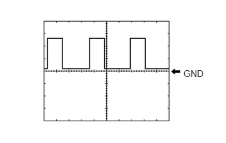
| A34-10 (NE) - A34-6 (DGND) |
Engine speed signal from ECM |
Idling after engine warmed up |
Pulse generation
(See waveform 1) |
| A34-13 (PB) - A34-3 (BRE2) |
Vacuum sensor assembly signal |
- Ignition switch ON
- Absolute pressure of 40 kPa (300 mmHg, 11.8 in.Hg) applied to vacuum sensor assembly
|
1.6 to 2.0 V |
- Ignition switch ON
- Absolute pressure of 60 kPa (450 mmHg, 17.7 in.Hg) applied to vacuum sensor assembly
|
2.2 to 2.6 V |
- Ignition switch ON
- Atmospheric pressure applied to vacuum sensor assembly
|
3.4 to 3.8 V |
| A34-14 (BRVC) - A34-6 (DGND) |
Vacuum sensor assembly power supply |
- Ignition switch ON
- Engine stopped
|
4.5 to 5.5 V |
| A34-17 (CLL) - A34-6 (DGND) |
Park/Neutral position switch assembly signal |
- Ignition switch ON
- Shift lever not in P or N
|
8 to 14 V |
- Ignition switch ON
- Shift lever in P or N
|
Below 3.0 V |
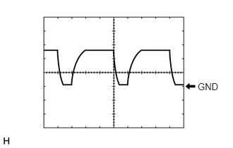
| A34-19 (DON2) - A34-6 (DGND) |
External backup boost converter (eco run vehicle converter assembly) signal |
Engine running |
Pulse generation
(see waveform 2) |
| A34-21 (STA) - A34-6 (DGND) |
Starter pinion operation signal |
Cranking |
6.0 V or more |
| H66-1 (IG31) - A34-6 (DGND) |
Backup boost converter signal |
Ignition switch ON |
10.5 to 16 V |
| H66-2 (B41) - A34-6 (DGND) |
Backup boost converter signal |
Always |
10.5 to 16 V |
| H66-3 (IG41) - A34-6 (DGND) |
Backup boost converter signal |
Ignition switch ON |
10.5 to 16 V |
| H66-5 (ECAN) - A34-6 (DGND) |
Stop and start system cancel switch (eco-run cancel switch assembly) signal |
- Ignition switch ON
- Stop and start system cancel switch (eco-run cancel switch assembly) pressed
|
Below 1.5 V |
- Ignition switch ON
- Stop and start system cancel switch (eco-run cancel switch assembly) not pressed
|
8 to 14 V |
| H66-6 (IG11) - A34-6 (DGND) |
Backup boost converter signal |
Ignition switch ON |
10.5 to 16 V |
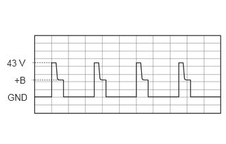
| H66-8 (EGND) - A33-8 (GND1) |
Oil pump with solenoid assembly directions signal |
One of the following conditions is met:
- Engine stopped by stop and start control
- Ignition switch ON (engine not running) and Active Test [Electromagnetic Oil Pump] being performed
|
Pulse generation
(See waveform 3) |
| H66-9 (EMOP) - A33-8 (GND1) |
Oil pump with solenoid assembly directions signal |
One of the following conditions is met:
- Engine stopped by stop and start control
- Ignition switch ON (engine not running) and Active Test [Electromagnetic Oil Pump] being performed
|
Pulse generation
(See waveform 3) |
| H66-10 (IG12) - A34-6 (DGND) |
Backup boost converter signal |
Ignition switch ON |
10.5 to 16 V |
| H66-11 (B43) - A34-6 (DGND) |
Backup boost converter signal |
Always |
10.5 to 16 V |
| H66-12 (B42) - A34-6 (DGND) |
Backup boost converter signal |
Always |
10.5 to 16 V |
| H66-16 (B12) - A34-6 (DGND) |
Backup boost converter signal |
Always |
10.5 to 16 V |
| H66-18 (IG2) - A34-6 (DGND) |
Push start switch signal |
Ignition switch ACC |
Below 1 V |
| Ignition switch ON |
9.5 to 14 V |
| H66-19 (ACC) - A34-6 (DGND) |
Push start switch signal |
Ignition switch off |
Below 1 V |
| Ignition switch ACC |
9.5 to 14 V |
| H66-21 (IG1) - A34-6 (DGND) |
Push start switch signal |
Ignition switch ACC |
Below 1 V |
| Ignition switch ON |
9.5 to 14 V |
| H66-24 (AC41) - A34-6 (DGND) |
Backup boost converter signal |
Ignition switch ACC |
10.5 to 16 V |
| H66-25 (IL41) - A34-6 (DGND) |
Backup boost converter signal |
Headlight dimmer switch (light control switch) in tail or head position |
10.5 to 16 V |
| H66-26 (IG13) - A34-6 (DGND) |
Backup boost converter signal |
Ignition switch ON |
10.5 to 16 V |