Terminals Of Ecu [12/2019 - 11/2023]
- CHECK INSTRUMENT PANEL JUNCTION BLOCK ASSEMBLY AND MAIN BODY ECU (MULTIPLEX NETWORK BODY ECU)
- Remove the main body ECU (multiplex network body ECU) from the instrument panel junction block assembly.
Refer to REMOVAL [12/2019 - 10/2022] , or refer to REMOVAL [10/2022 - 11/2023]
- Measure the resistance according to the value(s) in the table below.
HINT:
Measure the values on the wire harness side with the connectors connected.
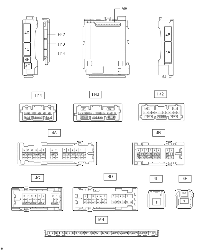
Terminal No. (Symbol) Terminal Description Condition Specified Condition H42-19 (GND2) - Body ground Ground Always Below 1 Ω - Reconnect the instrument panel junction block assembly connectors.
- Measure the voltage and resistance according to the value(s) in the table below.
Terminal No. (Symbol) Terminal Description Condition Specified Condition MB-11 (GND1) - Body ground Ground Always Below 1 Ω MB-30 (ACC) - Body ground ACC power supply Ignition switch ACC 11 to 14 V Ignition switch off Below 1 V MB-31 (BECU) - Body ground Auxiliary battery power supply Ignition switch off*1
Always*211 to 14 V MB-32 (IG) - Body ground IG power supply Ignition switch ON 11 to 14 V Ignition switch off Below 1 V - *1: for HV Model
- *2: for Gasoline Model
- Install the main body ECU (multiplex network body ECU) to the instrument panel junction block assembly.
Refer to INSTALLATION [12/2019 - 10/2022] , or refer to INSTALLATION [10/2022 - 11/2023]
- Measure the voltage according to the value(s) in the table below.
Terminal No. (Symbol) Terminal Description Condition Specified Condition H43-17 (LSWR) - Body ground Rear door RH unlock detection switch input Rear door RH unlocked → Rear door RH locked Below 1 V → 11 to 14 V H43-1 (FLCY) - Body ground Front door courtesy light switch (for LH) input Front door LH open → closed Below 1 V → 11 to 14 V H43-6 (FRCY) - Body ground Front door courtesy light switch (for RH) input Front door RH open → closed Below 1 V → 11 to 14 V 4D-24 (LCTY) - Body ground Rear door courtesy light switch (for LH) input Rear door LH open → closed Below 1 V → 11 to 14 V 4A-31 (RCTY) - Body ground Rear door courtesy light switch (for RH) input Rear door RH open → closed Below 1 V → 11 to 14 V 4D-34 (BCTY) - Body ground Back door courtesy light switch input Back door open → closed Below 1 V → 11 to 14 V 4B-13 (LSFL) - Body ground Front door LH unlock detection switch input Front door LH unlocked → locked Below 1 V → 11 to 14 V 4B-12 (LSFR) - Body ground Front door RH unlock detection switch input Front door RH unlocked → locked Below 1 V → 11 to 14 V 4B-14 (LSWL) - Body ground Rear door LH unlock detection switch input Rear door LH unlocked → Rear door LH locked Below 1 V → 11 to 14 V 4D-8 (ACT-) - Body ground Door lock motor unlock drive output Door control switch or driver door key cylinder off → on (unlock) Below 1 V → 11 to 14 V → Below 1 V 4D-9 (ACT-) - Body ground Door lock motor unlock drive output Door control switch or driver door key cylinder off → on (unlock) Below 1 V → 11 to 14 V → Below 1 V 4D-6 (ACT+) - Body ground Door lock motor lock drive output Door control switch or driver door key cylinder off → on (lock) Below 1 V → 11 to 14 V → Below 1 V 4B-4 (ACTD) - Body ground Door lock motor unlock drive output Door control switch or driver door key cylinder off → on (unlock) Below 1 V → 11 to 14 V → Below 1 V 4D-20 (TR+) - Body ground* Back door lock motor unlock drive output Back door opener switch off → on Below 1 V → 11 to 14 V → Below 1 V H44-17 (UL3) - Body ground Driver door key-linked unlock input Driver door key cylinder in neutral position → on (unlock) 11 to 14 V → Below 1 V H44-18 (L2) - Body ground Driver door key-linked lock input Driver door key cylinder in neutral position → on (lock) 11 to 14 V → Below 1 V 4B-16 (L1) - Body ground Door control switch assembly input Door control switch assembly off → on (lock) 11 to 14 V → Below 1 V 4B-39 (UL1) - Body ground Door control switch assembly input Door control switch assembly off → on (unlock) 11 to 14 V → Below 1 V 4A-7 (GSW) - Body ground Airbag sensor signal (collision detection signal) Ignition switch ON with airbag sensor assembly connector disconnected 4.3 to 5.5 V - *: w/o Power Back Door System
- Remove the main body ECU (multiplex network body ECU) from the instrument panel junction block assembly.
- CHECK CERTIFICATION ECU (SMART KEY ECU ASSEMBLY)
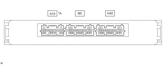
*A for Gasoline Model - - - Disconnect the H48 certification ECU (smart key ECU assembly) connector.
- Measure the voltage and resistance according to the value(s) in the table below.
HINT:
Measure the values on the wire harness side with the connector disconnected.
Terminal No. (Symbol) Terminal Description Condition Specified Condition H48-4 (+B) - Body ground Auxiliary battery power supply Ignition switch off*1
Always*211 to 14 V H48-18 (E) - Body ground Ground Always Below 1 Ω - *1: for HV Model
- *2: for Gasoline Model
- Reconnect the H48 certification ECU (smart key ECU assembly) connector.
- Measure the resistance and check for pulses according to the value(s) in the table below.
Terminal No. (Symbol) Terminal Description Condition Specified Condition M5-26 (TSW5) - Body ground Back door opener switch input Back door opener switch (open switch) off → on Below 1 Ω → pulse generation