Only Back Door cannot be Opened [11/2023 - ]: Procedure
- PERFORM ACTIVE TEST USING GTS (TRUNK LID / BACK DOOR OPEN)
- Perform the Active Test according to the display on the GTS.
Body Electrical > Main Body > Active Test
Tester Display Measurement Item Control Range Diagnostic Note Trunk Lid / Back Door Open Back door lock motor OFF/ON - Body Electrical > Main Body > Active Test
Tester Display Trunk Lid / Back Door Open OK
The back door lock assembly with courtesy light switch unlatches when ON is selected.
Result
Proceed to OK NG
Result:
OK
GO TO SMART KEY SYSTEM (for Entry Function). Refer to HOW TO PROCEED WITH TROUBLESHOOTING [11/2023 - ]
Result:
NG
See step 2
- Perform the Active Test according to the display on the GTS.
- INSPECT BACK DOOR LOCK WITH COURTESY LIGHT SWITCH ASSEMBLY
Refer to INSPECTION [12/2019 - ]
Result
Proceed to OK NG Result:
NG
REPLACE BACK DOOR LOCK WITH COURTESY LIGHT SWITCH ASSEMBLY. Refer to REMOVAL [12/2019 - ]
Result:
OK
See step 3
- CHECK HARNESS AND CONNECTOR (BACK DOOR LOCK WITH COURTESY LIGHT SWITCH ASSEMBLY - POWER DISTRIBUTION BOX ASSEMBLY AND BODY GROUND)
- Disconnect the W12 back door lock with courtesy light switch assembly connector.
- Disconnect the 8G power distribution box assembly connector.
- Measure the resistance according to the value(s) in the table below.
Standard Resistance
Tester Connection Condition Specified Condition W12-1 (ACT+) - 8G-39 Always Below 1 Ω W12-3 (D+) - 8G-2 Always Below 1 Ω W12-2 (ACT-) - Body ground Always Below 1 Ω W12-1 (ACT+) - Body ground Always 10 kΩ or higher 8G-39 - Body ground Always 10 kΩ or higher W12-3 (D+) - Body ground Always 10 kΩ or higher 8G-2 - Body ground Always 10 kΩ or higher Result
Proceed to OK NG
Result:
NG
REPAIR OR REPLACE HARNESS OR CONNECTOR
Result:
OK
See step 4
- INSPECT POWER DISTRIBUTION BOX ASSEMBLY
- Remove the power distribution box assembly.
Refer to REMOVAL [11/2023 - ]
- Remove the main body ECU (multiplex network body ECU) from the power distribution box assembly.
- Measure the resistance according to the value(s) in the table below.
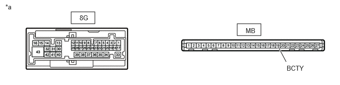
*a Component without harness connected
(Power Distribution Box Assembly)- - Standard Resistance
Tester Connection Condition Specified Condition MB-19 (BCTY) - 8G-2 Always Below 1 Ω Result
Proceed to OK NG
Result:
NG
REPLACE POWER DISTRIBUTION BOX ASSEMBLY. Refer to REMOVAL [11/2023 - ]
Result:
OK
See step 5
- Remove the power distribution box assembly.
- CHECK HARNESS AND CONNECTOR (POWER DISTRIBUTION BOX ASSEMBLY - AUXILIARY BATTERY AND BODY GROUND)
- Disconnect the 8H power distribution box assembly connectors.
- Measure the voltage according to the value(s) in the table below.
Standard Voltage
Tester Connection Switch Condition Specified Condition 8H-1 - Body ground Ignition switch off 11 to 14 V Result
Proceed to OK NG
Result:
NG
REPAIR OR REPLACE HARNESS OR CONNECTOR
Result:
OK
See step 6
- REPLACE POWER DISTRIBUTION BOX ASSEMBLY
Refer to REMOVAL [11/2023 - ]
Result
Proceed to NEXT Result:
NEXT
See step 7
- CHECK BACK DOOR OPEN OPERATION
Result:
OK
END
Result:
NG
REPLACE MAIN BODY ECU (MULTIPLEX NETWORK BODY ECU). Refer to REMOVAL [11/2023 - ]