System Description [10/2022 - ]
- COMMUNICATION SYSTEM OUTLINE
- CAN communication system
- The panoramic view monitor system uses CAN communication for data communications between the parking assist ECU and each ECU.
- If a problem occurs in the CAN communication line, the parking assist ECU outputs a CAN communication malfunction DTC. (To check, use the GTS.)
- When there is a problem with the CAN communication line, the parking assist ECU stores a CAN communication malfunction DTC. (Perform a check of the radio and display receiver assembly using the diagnosis screen)
For HV Model: Refer to DIAGNOSIS SYSTEM [10/2022 - 11/2023] , or refer to DIAGNOSIS SYSTEM [11/2023 - ]
For Gasoline Model: Refer to DIAGNOSIS SYSTEM [10/2022 - 11/2023] , or refer to DIAGNOSIS SYSTEM [11/2023 - ]
- If a CAN communication line malfunction DTC is output, repair the malfunction in the communication line and troubleshoot the panoramic view monitor system when data communication is normal.
- Since the CAN communication line has its own length and route, it cannot be repaired temporarily with a bypass wire, etc.
- CAN communication system
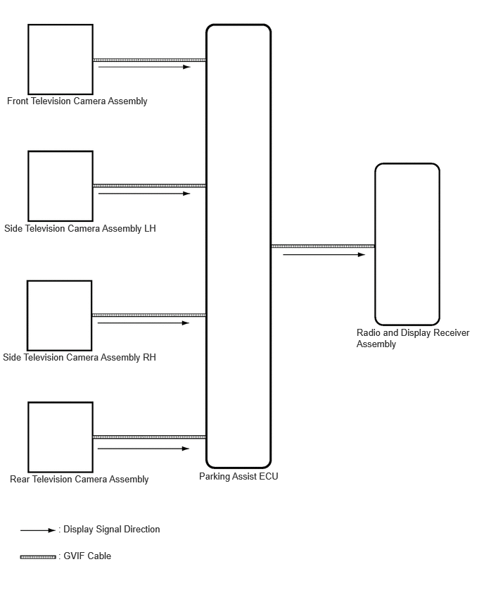
- VIDEO SIGNALS
- Video signal circuit
- Video signals from each camera are input into the parking assist ECU via GVIF cable.
- Video signals from the parking assist ECU are input into the radio and display receiver assembly via GVIF cable.
- Screen display
- Video signals input from each camera are processed in the parking assist ECU and displayed on the radio and display receiver assembly as the panoramic view monitor system screen.
- Video signal circuit
- DIAGNOSTIC FUNCTION OUTLINE
- This panoramic view monitor system has a diagnostic function displayed in the radio and display receiver assembly. This function enables the calibration (adjustment and verification) of the panoramic view monitor system.
Refer to DIAGNOSIS SYSTEM [10/2022 - ]
HINT:
The panoramic view monitor system has a diagnosis function which can check each signal input to the parking assist ECU and adjust and monitor the panoramic view monitor system.
- The panoramic view monitor system can check the following items by using the GTS.
Item Proceed to DTC - RoB - Data List / Active Test Refer to DATA LIST / ACTIVE TEST [10/2022 - ] SSR -
- This panoramic view monitor system has a diagnostic function displayed in the radio and display receiver assembly. This function enables the calibration (adjustment and verification) of the panoramic view monitor system.
- CALIBRATION
- Use the panoramic view monitor system diagnosis screen for calibration and checking of the panoramic view monitor system.
Refer to DIAGNOSIS SYSTEM [10/2022 - ]
NOTE:Part replacement and work performed during servicing may require calibration of the panoramic view monitor system and other systems.
Refer to CALIBRATION [10/2022 - 11/2023] , or refer to CALIBRATION [11/2023 - ]
- Use the panoramic view monitor system diagnosis screen for calibration and checking of the panoramic view monitor system.