Climate Control Seat System does not Operate [11/2023 - ]: Procedure
- CHECK CLIMATE CONTROL SEAT OPERATION
- Check the climate control seat operation.
Refer to ON-VEHICLE INSPECTION [12/2019 - ]
Result
Result Proceed to Climate control seat does not operate (for LH) A Climate control seat does not operate (for RH) B Both climate control seats do not operate C
Result:
B
See step 13
Result:
C
See step 24
Result:
A
See step 2
- Check the climate control seat operation.
- PERFORM ACTIVE TEST USING GTS
- Perform the Active Test according to the display on the GTS.
Body Electrical > Air Conditioner > Active Test
Tester Display Measurement Item Control Range Diagnostic Note Front Left Seat Blower Front LH seat blower operation OFF or ON - Body Electrical > Air Conditioner > Active Test
Tester Display Front Left Seat Blower Result
Result Proceed to Both front LH seat cushion blower and front LH seatback blower operate A Only front LH seatback blower does not operate B Only front LH seat cushion blower does not operate C Both front LH seat cushion blower and front LH seatback blower do not operate D
Result:
A
GO TO AIR CONDITIONING SYSTEM
For HV Model: Refer to HOW TO PROCEED WITH TROUBLESHOOTING [11/2023 - ]
For Gasoline Model: Refer to HOW TO PROCEED WITH TROUBLESHOOTING [11/2023 - ]
Result:
C
REPLACE SEAT CUSHION CLIMATE CONTROL BLOWER ASSEMBLY LH. Refer to DISASSEMBLY [11/2023 - ]
Result:
D
See step 6
Result:
B
See step 3
- Perform the Active Test according to the display on the GTS.
- CHECK HARNESS AND CONNECTOR (SEAT CUSHION CLIMATE CONTROL BLOWER ASSEMBLY LH - SEATBACK CLIMATE CONTROL BLOWER LH)
- Disconnect the g3 seatback climate control blower LH connector.
- Disconnect the e20 seat cushion climate control blower assembly LH connector.
- Measure the resistance according to the value(s) in the table below.
Standard Resistance
Tester Connection Condition Specified Condition g3-1 (IG) - e20-5 (CTB) Always Below 1 Ω g3-1 (IG) or e20-5 (CTB) - Body ground Always 10 kΩ or higher g3-3 (BFB+) - e20-6 (BBS) Always Below 1 Ω g3-3 (BFB+) or e20-6 (BBS) - Body ground Always 10 kΩ or higher g3-4 (GND) - e20-4 (BFB-) Always Below 1 Ω g3-4 (GND) or e20-4 (BFB-) - Body ground Always 10 kΩ or higher Result
Proceed to OK NG
Result:
NG
REPAIR OR REPLACE HARNESS OR CONNECTOR
Result:
OK
See step 4
- REPLACE SEATBACK CLIMATE CONTROL BLOWER LH
- Temporarily replace the seatback climate control blower LH with a new or known good one.
Refer to DISASSEMBLY [11/2023 - ]
Result
Proceed to NEXT
Result:
NEXT
See step 5
- Temporarily replace the seatback climate control blower LH with a new or known good one.
- CHECK CLIMATE CONTROL SEAT OPERATION
- Check the climate control seat operation.
Refer to ON-VEHICLE INSPECTION [12/2019 - ]
OK
The climate control seat operates normally.
Result
Proceed to OK NG
Result:
OK
END (SEATBACK CLIMATE CONTROL BLOWER LH WAS DEFECTIVE)
Result:
NG
REPLACE SEAT CUSHION CLIMATE CONTROL BLOWER ASSEMBLY LH. Refer to DISASSEMBLY [11/2023 - ]
- Check the climate control seat operation.
- INSPECT S/HTR F/L RELAY
Refer to ON-VEHICLE INSPECTION [12/2019 - ]
Result
Proceed to OK NG Result:
NG
REPLACE S/HTR F/L RELAY
Result:
OK
See step 7
- CHECK HARNESS AND CONNECTOR (POWER SUPPLY - S/HTR F/L RELAY)
- Measure the voltage according to the value(s) in the table below.
Standard Voltage
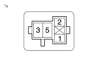
Tester Connection Condition Specified Condition S/HTR F/L relay holder terminal 1 - Body ground Ignition switch ON 11 V to 14 V S/HTR F/L relay holder terminal 3 - Body ground Always 11 V to 14 V *a S/HTR F/L Relay Holder Result
Proceed to OK NG
Result:
NG
REPAIR OR REPLACE HARNESS OR CONNECTOR
Result:
OK
See step 8
- Measure the voltage according to the value(s) in the table below.
- CHECK HARNESS AND CONNECTOR (S/HTR F/L RELAY - SEAT CUSHION CLIMATE CONTROL BLOWER ASSEMBLY LH)
- Disconnect the e20 seat cushion climate control blower assembly LH connector.
- Measure the resistance according to the value(s) in the table below.
Standard Resistance
Tester Connection Condition Specified Condition S/HTR F/L relay holder terminal 5 - e20-1 (IG) Always Below 1 Ω S/HTR F/L relay holder terminal 5 or e20-1 (IG) - Body ground Always 10 kΩ or higher Result
Proceed to OK NG
Result:
NG
REPAIR OR REPLACE HARNESS OR CONNECTOR
Result:
OK
See step 9
- CHECK HARNESS AND CONNECTOR (S/HTR F/L RELAY - BODY GROUND)
- Measure the resistance according to the value(s) in the table below.
Standard Resistance
Tester Connection Condition Specified Condition S/HTR F/L relay holder terminal 2 - Body ground Always Below 1 Ω Result
Proceed to OK NG
Result:
NG
REPAIR OR REPLACE HARNESS OR CONNECTOR
Result:
OK
See step 10
- Measure the resistance according to the value(s) in the table below.
- CHECK HARNESS AND CONNECTOR (IG POWER SUPPLY - SEAT CUSHION CLIMATE CONTROL BLOWER ASSEMBLY LH - BODY GROUND)
- Disconnect the e20 seat cushion climate control blower assembly LH connector.
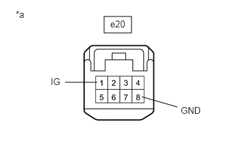
*a Front view of wire harness connector
(to Seat Cushion Climate Control Blower Assembly LH) - Measure the voltage and resistance according to the value(s) in the table below.
Standard Voltage
Tester Connection Condition Specified Condition e20-1 (IG) - Body ground Ignition switch ON 11 to 14 V e20-1 (IG) - Body ground Ignition switch off Below 1 V Standard Resistance
Tester Connection Condition Specified Condition e20-8 (GND) - Body ground Always Below 1 Ω Result
Proceed to OK NG
Result:
NG
REPAIR OR REPLACE HARNESS OR CONNECTOR
Result:
OK
See step 11
- Disconnect the e20 seat cushion climate control blower assembly LH connector.
- CHECK HARNESS AND CONNECTOR (SEAT CUSHION CLIMATE CONTROL BLOWER ASSEMBLY LH - AIR CONDITIONING AMPLIFIER ASSEMBLY)
- Disconnect the H62 air conditioning amplifier assembly connector.
- Measure the resistance according to the value(s) in the table below.
Standard Resistance
Tester Connection Condition Specified Condition e20-7 (SIGN) - H62-14 (LOUT) Always Below 1 Ω e20-7 (SIGN) or H62-14 (LOUT) - Body ground Always 10 kΩ or higher Result
Proceed to OK NG
Result:
NG
REPAIR OR REPLACE HARNESS OR CONNECTOR
Result:
OK
See step 12
- CHECK AIR CONDITIONING AMPLIFIER ASSEMBLY
- Reconnect the H62 air conditioning amplifier assembly connector.
*a Component with harness connected
(Air Conditioning Amplifier Assembly) - Reconnect the e20 seat cushion climate control blower assembly LH connector.
- Using an oscilloscope, check the input signal waveform.MEASUREMENT CONDITION
Item Content Tester Connection H62-14 (LOUT) - Body ground Tool Setting 1 V/DIV., 0.5 ms/DIV. Vehicle Condition - Ignition switch ON
- Climate control switch on
OK
Waveform is similar to that shown in the illustration.
Result
Proceed to OK NG
Result:
OK
REPLACE SEAT CUSHION CLIMATE CONTROL BLOWER ASSEMBLY LH. Refer to DISASSEMBLY [11/2023 - ]
Result:
NG
REPLACE AIR CONDITIONING AMPLIFIER ASSEMBLY. Refer to REMOVAL [11/2023 - ]
- Reconnect the H62 air conditioning amplifier assembly connector.
- PERFORM ACTIVE TEST USING GTS
- Perform the Active Test according to the display on the GTS.
Body Electrical > Air Conditioner > Active Test
Tester Display Measurement Item Control Range Diagnostic Note Front Right Seat Blower Front RH seat blower operation OFF or ON - Body Electrical > Air Conditioner > Active Test
Tester Display Front Right Seat Blower Result
Result Proceed to Both front RH seat cushion blower and front RH seatback blower operate A Only front RH seatback blower does not operate B Only front RH seat cushion blower does not operate C Both front RH seat cushion blower and front RH seatback blower do not operate D
Result:
A
GO TO AIR CONDITIONING SYSTEM
For HV Model: Refer to HOW TO PROCEED WITH TROUBLESHOOTING [11/2023 - ]
For Gasoline Model: Refer to HOW TO PROCEED WITH TROUBLESHOOTING [11/2023 - ]
Result:
C
REPLACE SEAT CUSHION CLIMATE CONTROL BLOWER ASSEMBLY RH. Refer to DISASSEMBLY [11/2023 - ]
Result:
D
See step 17
Result:
B
See step 14
- Perform the Active Test according to the display on the GTS.
- CHECK HARNESS AND CONNECTOR (SEATBACK CLIMATE CONTROL BLOWER RH - SEAT CUSHION CLIMATE CONTROL BLOWER ASSEMBLY RH)
- Disconnect the g1 seatback climate control blower RH connector.
- Disconnect the e9 seat cushion climate control blower assembly RH connector.
- Measure the resistance according to the value(s) in the table below.
Standard Resistance
Tester Connection Condition Specified Condition g1-1 (IG) - e9-5 (CTB) Always Below 1 Ω g1-1 (IG) or e9-5 (CTB) - Body ground Always 10 kΩ or higher g1-3 (BFB+) - e9-6 (BBS) Always Below 1 Ω g1-3 (BFB+) or e9-6 (BBS) - Body ground Always 10 kΩ or higher g1-4 (GND) - e9-4 (BFB-) Always Below 1 Ω g1-4 (GND) or e9-4 (BFB-) - Body ground Always 10 kΩ or higher Result
Proceed to OK NG
Result:
NG
REPAIR OR REPLACE HARNESS OR CONNECTOR
Result:
OK
See step 15
- REPLACE SEATBACK CLIMATE CONTROL BLOWER RH
- Temporarily replace the seatback climate control blower RH with a new or known good one.
Refer to DISASSEMBLY [11/2023 - ]
Result
Proceed to NEXT
Result:
NEXT
See step 16
- Temporarily replace the seatback climate control blower RH with a new or known good one.
- CHECK CLIMATE CONTROL SEAT OPERATION
- Check the climate control seat operation.
Refer to ON-VEHICLE INSPECTION [12/2019 - ]
OK
The climate control seat operates normally.
Result
Proceed to OK NG
Result:
OK
END (SEATBACK CLIMATE CONTROL BLOWER RH WAS DEFECTIVE)
Result:
NG
REPLACE SEAT CUSHION CLIMATE CONTROL BLOWER ASSEMBLY RH. Refer to DISASSEMBLY [11/2023 - ]
- Check the climate control seat operation.
- INSPECT S/HTR F/R RELAY
Refer to ON-VEHICLE INSPECTION [12/2019 - ]
Result
Proceed to OK NG Result:
NG
REPLACE S/HTR F/R RELAY
Result:
OK
See step 18
- CHECK HARNESS AND CONNECTOR (POWER SUPPLY - S/HTR F/R RELAY)
- Measure the voltage according to the value(s) in the table below.
Standard Voltage
Tester Connection Condition Specified Condition S/HTR F/R relay holder terminal 1 - Body ground Ignition switch ON 11 V to 14 V S/HTR F/R relay holder terminal 3 - Body ground Always 11 V to 14 V *a S/HTR F/R Relay Holder Result
Proceed to OK NG
Result:
NG
REPAIR OR REPLACE HARNESS OR CONNECTOR
Result:
OK
See step 19
- Measure the voltage according to the value(s) in the table below.
- CHECK HARNESS AND CONNECTOR (S/HTR F/R RELAY - SEAT CUSHION CLIMATE CONTROL BLOWER ASSEMBLY RH)
- Disconnect the e9 seat cushion climate control blower assembly RH connector.
- Measure the resistance according to the value(s) in the table below.
Standard Resistance
Tester Connection Condition Specified Condition S/HTR F/R relay holder terminal 5 - e9-1 (IG) Always Below 1 Ω S/HTR F/R relay holder terminal 5 or e9-1 (IG) - Body ground Always 10 kΩ or higher Result
Proceed to OK NG
Result:
NG
REPAIR OR REPLACE HARNESS OR CONNECTOR
Result:
OK
See step 20
- CHECK HARNESS AND CONNECTOR (S/HTR F/R RELAY - BODY GROUND)
- Measure the resistance according to the value(s) in the table below.
Standard Resistance
Tester Connection Condition Specified Condition S/HTR F/R relay holder terminal 2 - Body ground Always Below 1 Ω Result
Proceed to OK NG
Result:
NG
REPAIR OR REPLACE HARNESS OR CONNECTOR
Result:
OK
See step 21
- Measure the resistance according to the value(s) in the table below.
- CHECK HARNESS AND CONNECTOR (IG POWER SUPPLY - SEAT CUSHION CLIMATE CONTROL BLOWER ASSEMBLY RH - BODY GROUND)
- Disconnect the e9 seat cushion climate control blower assembly RH connector.
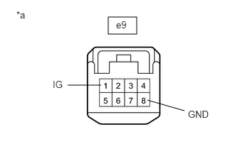
*a Front view of wire harness connector
(to Seat Cushion Climate Control Blower Assembly RH) - Measure the voltage and resistance according to the value(s) in the table below.
Standard Voltage
Tester Connection Condition Specified Condition e9-1 (IG) - Body ground Ignition switch ON 11 to 14 V e9-1 (IG) - Body ground Ignition switch off Below 1 V Standard Resistance
Tester Connection Condition Specified Condition e9-8 (GND) - Body ground Always Below 1 Ω Result
Proceed to OK NG
Result:
NG
REPAIR OR REPLACE HARNESS OR CONNECTOR
Result:
OK
See step 22
- Disconnect the e9 seat cushion climate control blower assembly RH connector.
- CHECK HARNESS AND CONNECTOR (SEAT CUSHION CLIMATE CONTROL BLOWER ASSEMBLY RH - AIR CONDITIONING AMPLIFIER ASSEMBLY)
- Disconnect the H62 air conditioning amplifier assembly connector.
- Measure the resistance according to the value(s) in the table below.
Standard Resistance
Tester Connection Condition Specified Condition e9-7 (SIGN) - H62-13 (ROUT) Always Below 1 Ω e9-7 (SIGN) or H62-13 (ROUT) - Body ground Always 10 kΩ or higher Result
Proceed to OK NG
Result:
NG
REPAIR OR REPLACE HARNESS OR CONNECTOR
Result:
OK
See step 23
- CHECK AIR CONDITIONING AMPLIFIER ASSEMBLY
- Reconnect the H62 air conditioning amplifier assembly connector.
- Reconnect the e9 seat cushion climate control blower assembly RH connector.
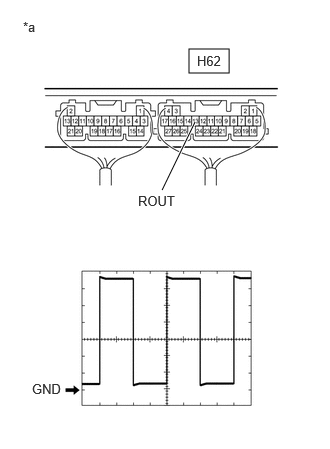
*a Component with harness connected
(Air Conditioning Amplifier Assembly) - Using an oscilloscope, check the input signal waveform.MEASUREMENT CONDITION
Item Content Tester Connection H62-13 (ROUT) - Body ground Tool Setting 1 V/DIV., 0.5 ms/DIV. Vehicle Condition - Ignition switch ON
- Climate control switch on
OK
Waveform is similar to that shown in the illustration.
Result
Proceed to OK NG
Result:
OK
REPLACE SEAT CUSHION CLIMATE CONTROL BLOWER ASSEMBLY RH. Refer to DISASSEMBLY [11/2023 - ]
Result:
NG
REPLACE AIR CONDITIONING AMPLIFIER ASSEMBLY. Refer to REMOVAL [11/2023 - ]
- REPLACE CLIMATE CONTROL SWITCH (AIR CONDITIONING CONTROL ASSEMBLY)
- Temporarily replace the climate control switch (air conditioning control assembly) with a new or known good one.
Refer to REMOVAL [12/2019 - ]
Result
Proceed to NEXT
Result:
NEXT
See step 25
- Temporarily replace the climate control switch (air conditioning control assembly) with a new or known good one.
- CHECK CLIMATE CONTROL SEAT OPERATION
- Check the climate control seat operation.
Refer to ON-VEHICLE INSPECTION [12/2019 - ]
OK
The climate control seat operates normally.
Result
Proceed to OK NG
Result:
OK
END (CLIMATE CONTROL SWITCH (AIR CONDITIONING CONTROL ASSEMBLY) WAS DEFECTIVE)
Result:
NG
REPLACE AIR CONDITIONING AMPLIFIER ASSEMBLY. Refer to REMOVAL [11/2023 - ]
- Check the climate control seat operation.