Seat Heater for Front Left Seat does not Operate [11/2023 - ]: Procedure
- PERFORM ACTIVE TEST USING GTS
- Perform the Active Test according to the display on the GTS.
Body Electrical > Air Conditioner > Active Test
Tester Display Measurement Item Control Range Diagnostic Note Front Left Seat Heater Front seat LH side seat heater operation OFF or ON - Body Electrical > Air Conditioner > Active Test
Tester Display Front Left Seat Heater OK
Front seat LH side seat heater operates normally.
Result
Proceed to OK NG
Result:
OK
GO TO AIR CONDITIONING SYSTEM
for HV Model: Refer to HOW TO PROCEED WITH TROUBLESHOOTING [11/2023 - ]
for Gasoline Model: Refer to HOW TO PROCEED WITH TROUBLESHOOTING [11/2023 - ]
Result:
NG
See step 2
- Perform the Active Test according to the display on the GTS.
- CHECK HARNESS AND CONNECTOR (POWER SUPPLY - SEAT HEATER CONTROL SUB-ASSEMBLY LH)
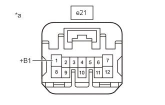
- Disconnect the e21 seat heater control sub-assembly LH connector.
*a Front view of wire harness connector
(to Seat Heater Control Sub-assembly LH) - Measure the voltage according to the value(s) in the table below.
Standard Voltage
Tester Connection Condition Specified Condition e21-1 (+B1) - Body ground Ignition switch ON 11 to 14 V e21-1 (+B1) - Body ground Ignition switch off Below 1 V Result
Proceed to OK NG
Result:
NG
See step 9
Result:
OK
See step 3
- Disconnect the e21 seat heater control sub-assembly LH connector.
- CHECK HARNESS AND CONNECTOR (AIR CONDITIONING AMPLIFIER ASSEMBLY - SEAT HEATER CONTROL SUB-ASSEMBLY LH)
- Disconnect the H64 air conditioning amplifier assembly connector.
- Measure the resistance according to the value(s) in the table below.
Standard Resistance
Tester Connection Condition Specified Condition H64-13 (SM1L) - e21-5 (SWR) Always Below 1 Ω H64-13 (SM1L) or e21-5 (SWR) - Body ground Always 10 kΩ or higher Result
Proceed to OK NG
Result:
NG
REPAIR OR REPLACE HARNESS OR CONNECTOR
Result:
OK
See step 4
- CHECK HARNESS AND CONNECTOR (SEAT HEATER CONTROL SUB-ASSEMBLY LH - FRONT SEAT CUSHION HEATER ASSEMBLY LH AND BODY GROUND)
- Disconnect the e19 front seat cushion heater assembly LH connector.
- Measure the resistance according to the value(s) in the table below.
Standard Resistance
Tester Connection Condition Specified Condition e21-7 (HTR1) - e19-1 Always Below 1 Ω e21-7 (HTR1) or e19-1 - Body ground Always 10 kΩ or higher e21-10 (E) - e19-6 Always Below 1 Ω e21-10 (E) or e19-6 - Body ground Always 10 kΩ or higher e19-2 - Body ground Always Below 1 Ω Result
Proceed to OK NG
Result:
NG
REPAIR OR REPLACE HARNESS OR CONNECTOR
Result:
OK
See step 5
- INSPECT FRONT SEAT CUSHION HEATER ASSEMBLY LH
Refer to INSPECTION [12/2019 - ]
Result
Proceed to OK NG Result:
NG
REPLACE FRONT SEAT CUSHION HEATER ASSEMBLY LH. Refer to REMOVAL [11/2023 - ]
Result:
OK
See step 6
- INSPECT FRONT SEATBACK HEATER ASSEMBLY LH
Refer to INSPECTION [12/2019 - ]
Result
Proceed to OK NG Result:
NG
REPLACE FRONT SEATBACK HEATER ASSEMBLY LH. Refer to REMOVAL [11/2023 - ]
Result:
OK
See step 7
- REPLACE SEAT HEATER CONTROL SUB-ASSEMBLY LH
- Temporarily replace the seat heater control sub-assembly LH with a new or known good one.
Refer to REMOVAL [11/2023 - ]
Result
Proceed to NEXT
Result:
NEXT
See step 8
- Temporarily replace the seat heater control sub-assembly LH with a new or known good one.
- CHECK FRONT SEAT HEATER OPERATION
- Check the front seat LH side seat heater operation.
Refer to OPERATION CHECK [12/2019 - ]
OK
Front seat LH side seat heater operates normally.
Result
Proceed to OK NG
Result:
OK
END (SEAT HEATER CONTROL SUB-ASSEMBLY LH WAS DEFECTIVE)
Result:
NG
REPLACE AIR CONDITIONING AMPLIFIER ASSEMBLY. Refer to REMOVAL [11/2023 - ]
- Check the front seat LH side seat heater operation.
- INSPECT S/HTR F/L RELAY
Refer to ON-VEHICLE INSPECTION [12/2019 - ]
Result
Proceed to OK NG Result:
NG
REPLACE S/HTR F/L RELAY
Result:
OK
See step 10
- CHECK HARNESS AND CONNECTOR (POWER SUPPLY - S/HTR F/L RELAY)
- Measure the voltage according to the value(s) in the table below.
Standard Voltage
Tester Connection Condition Specified Condition S/HTR F/L relay holder terminal 1 - Body ground Ignition switch ON 11 V to 14 V S/HTR F/L relay holder terminal 1 - Body ground Ignition switch off Below 1 V S/HTR F/L relay holder terminal 3 - Body ground Ignition switch off 11 V to 14 V Result
Proceed to OK NG
Result:
NG
REPAIR OR REPLACE HARNESS OR CONNECTOR
Result:
OK
See step 11
- Measure the voltage according to the value(s) in the table below.
- CHECK HARNESS AND CONNECTOR (S/HTR F/L RELAY - SEAT HEATER CONTROL SUB-ASSEMBLY LH)
- Measure the resistance according to the value(s) in the table below.
Standard Resistance
Tester Connection Condition Specified Condition S/HTR F/L relay holder terminal 5 - e21-1 (+B1) Always Below 1 Ω S/HTR F/L relay holder terminal 5 or e21-1 (+B1) - Body ground Always 10 kΩ or higher Result
Proceed to OK NG
Result:
NG
REPAIR OR REPLACE HARNESS OR CONNECTOR
Result:
OK
See step 12
- Measure the resistance according to the value(s) in the table below.
- CHECK HARNESS AND CONNECTOR (S/HTR F/L RELAY - BODY GROUND)
- Measure the resistance according to the value(s) in the table below.
Standard Resistance
Tester Connection Condition Specified Condition S/HTR F/L relay holder terminal 2 - Body ground Always Below 1 Ω Result
Proceed to OK NG
Result:
OK
USE SIMULATION METHOD TO CHECK. Refer to HOW TO PROCEED WITH TROUBLESHOOTING [12/2019 - ]
Result:
NG
REPAIR OR REPLACE HARNESS OR CONNECTOR
- Measure the resistance according to the value(s) in the table below.