Seat Heater for Rear Right Seat does not Operate [12/2019 - 10/2022]: Procedure
- CLEAR DTC
Result:
NEXT
See step 2
- CHECK FOR DTC
- Check for DTCs.
Body Electrical > Air Conditioner > Trouble Codes
OK
DTC B14B3 or B14C2 is not output.
Result
Proceed to OK NG
Result:
NG
GO TO DIAGNOSTIC TROUBLE CODE CHART
B14C2: Refer to DIAGNOSTIC TROUBLE CODE CHART [12/2019 - 11/2023]
B14B3 (for HV Model): Refer to DIAGNOSTIC TROUBLE CODE CHART [12/2019 - 10/2021] , or refer to DIAGNOSTIC TROUBLE CODE CHART [10/2021 - 10/2022]
B14B3 (for Gasoline Model with Automatic Air Conditioning System): Refer to DTC B14B3: Lost Communication with Rear Panel LIN [12/2019 - 11/2023]
B14B3 (for Gasoline Model with Manual Air Conditioning System): Refer to TERMINALS OF ECU [12/2019 - 10/2022]
Result:
OK
See step 3
- Check for DTCs.
- PERFORM ACTIVE TEST USING GTS
- Perform the Active Test according to the display on the GTS.
Body Electrical > Air Conditioner > Active Test
Tester Display Measurement Item Control Range Diagnostic Note Rear Right Seat Heater Rear seat RH side seat heater operation OFF or ON - Body Electrical > Air Conditioner > Active Test
Tester Display Rear Right Seat Heater OK
The seat heater operates normally.
Result
Proceed to OK NG
Result:
OK
REPLACE REAR SEAT HEATER SWITCH (AIR CONDITIONING CONTROL ASSEMBLY NO. 2). Refer to REMOVAL [12/2019 - ]
Result:
NG
See step 4
- Perform the Active Test according to the display on the GTS.
- CHECK HARNESS AND CONNECTOR (POWER SUPPLY - SEAT HEATER CONTROL SUB-ASSEMBLY RH (FOR REAR))
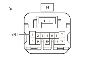
- Disconnect the f4 seat heater control sub-assembly RH (for rear) connector.
*a Front view of wire harness connector
(to Seat Heater Control Sub-assembly RH (for Rear)) - Measure the voltage according to the value(s) in the table below.
Standard Voltage
Tester Connection Condition Specified Condition f4-1 (+B1) - Body ground Ignition switch ON 11 to 14 V f4-1 (+B1) - Body ground Ignition switch off Below 1 V Result
Proceed to OK NG
Result:
NG
See step 12
Result:
OK
See step 5
- Disconnect the f4 seat heater control sub-assembly RH (for rear) connector.
- INSPECT REAR SEATBACK HEATER RH (SEAT HEATER ASSEMBLY)
for Captain Seat Type: Refer to INSPECTION [12/2019 - ]
for 60/40 Split Seat Type RH Side: Refer to INSPECTION [12/2019 - ]
Result
Proceed to OK NG Result:
NG
REPLACE REAR SEATBACK HEATER RH (SEAT HEATER ASSEMBLY)
for Captain Seat Type: Refer to REMOVAL [12/2019 - ]
for 60/40 Split Seat Type RH Side: Refer to REMOVAL [12/2019 - ]
Result:
OK
See step 6
- INSPECT REAR SEAT CUSHION HEATER RH (SEAT HEATER ASSEMBLY)
for Captain Seat Type: Refer to INSPECTION [12/2019 - ]
for 60/40 Split Seat Type RH Side: Refer to INSPECTION [12/2019 - ]
Result
Proceed to OK NG Result:
NG
REPLACE REAR SEAT CUSHION HEATER RH (SEAT HEATER ASSEMBLY)
for Captain Seat Type: Refer to REMOVAL [12/2019 - ]
for 60/40 Split Seat Type RH Side: Refer to REMOVAL [12/2019 - ]
Result:
OK
See step 7
- CHECK HARNESS AND CONNECTOR (REAR SEAT CUSHION HEATER RH (SEAT HEATER ASSEMBLY) - BODY GROUND)
- Measure the resistance according to the value(s) in the table below.
Standard Resistance
Tester Connection Condition Specified Condition f1-4 - Body ground Always Below 1 Ω Result
Proceed to OK NG
Result:
NG
REPAIR OR REPLACE HARNESS OR CONNECTOR
Result:
OK
See step 8
- Measure the resistance according to the value(s) in the table below.
- CHECK HARNESS AND CONNECTOR (SEAT HEATER CONTROL SUB-ASSEMBLY RH (FOR REAR) - REAR SEAT CUSHION HEATER RH (SEAT HEATER ASSEMBLY))
- Disconnect the f4 seat heater control sub-assembly RH (for rear) connector.
- Measure the resistance according to the value(s) in the table below.
Standard Resistance
Tester Connection Condition Specified Condition f4-7 (HTR1) - f1-1 Always Below 1 Ω f4-7 (HTR1) or f1-1 - Body ground Always 10 kΩ or higher f4-10 (E) - f1-3 Always Below 1 Ω f4-10 (E) or f1-3 - Body ground Always 10 kΩ or higher Result
Proceed to OK NG
Result:
NG
REPAIR OR REPLACE HARNESS OR CONNECTOR
Result:
OK
See step 9
- INSPECT SEAT HEATER CONTROL SUB-ASSEMBLY RH (FOR REAR)
- Reconnect the f4 seat heater control sub-assembly RH (for rear) connector.
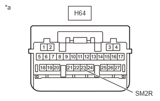
- Disconnect the H64 air conditioning amplifier assembly connector.
*a Front view of wire harness connector
(to Air Conditioning Amplifier Assembly) - Measure the voltage according to the value(s) in the table below.
Standard Voltage
Tester Connection Condition Specified Condition H64-23 (SM2R) - Body ground Ignition switch ON 5 to 13 V Result
Proceed to OK NG
Result:
NG
See step 11
Result:
OK
See step 10
- CHECK AIR CONDITIONING AMPLIFIER ASSEMBLY
- Reconnect the f4 seat heater control sub-assembly RH (for rear) connector.
- Reconnect the H64 air conditioning amplifier assembly connector.
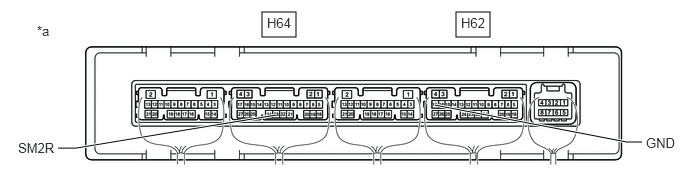
- Remove the air conditioning amplifier assembly with its connectors still connected.
Refer to REMOVAL [12/2019 - 10/2022]
- Measure the voltage according to the value(s) in the table below.
*a Component with harness connected
(Air Conditioning Amplifier Assembly)- - Standard Voltage
Tester Connection Condition Specified Condition H64-23 (SM2R) - H62-17 (GND) Ignition switch ON, rear seat heater switch (air conditioning control assembly No. 2) on (LO) Below 1 V Result
Proceed to OK NG
Result:
OK
REPLACE SEAT HEATER CONTROL SUB-ASSEMBLY RH (FOR REAR). Refer to REMOVAL [12/2019 - ]
Result:
NG
REPLACE AIR CONDITIONING AMPLIFIER ASSEMBLY. Refer to REMOVAL [12/2019 - 10/2022]
- CHECK HARNESS AND CONNECTOR (AIR CONDITIONING AMPLIFIER ASSEMBLY - SEAT HEATER CONTROL SUB-ASSEMBLY RH (FOR REAR))
- Disconnect the f4 seat heater control sub-assembly RH (for rear) connector.
- Measure the resistance according to the value(s) in the table below.
Standard Resistance
Tester Connection Condition Specified Condition H64-23 (SM2R) - f4-5 (SWR) Always Below 1 Ω H64-23 (SM2R) or f4-5 (SWR) - Body ground Always 10 kΩ or higher Result
Proceed to OK NG
Result:
OK
REPLACE SEAT HEATER CONTROL SUB-ASSEMBLY RH (FOR REAR). Refer to REMOVAL [12/2019 - ]
Result:
NG
REPAIR OR REPLACE HARNESS OR CONNECTOR
- INSPECT S/HTR R/R RELAY
- Inspect the S/HTR R/R relay.
Refer to ON-VEHICLE INSPECTION [12/2019 - ]
Result
Proceed to OK NG
Result:
NG
REPAIR OR REPLACE HARNESS OR CONNECTOR
Result:
OK
See step 13
- Inspect the S/HTR R/R relay.
- CHECK HARNESS AND CONNECTOR (POWER SUPPLY - S/HTR R/R RELAY)
- Measure the voltage according to the value(s) in the table below.
Standard Voltage
Tester Connection Condition Specified Condition S/HTR R/R relay holder terminal 1 - Body ground Ignition switch ON 11 V to 14 V S/HTR R/R relay holder terminal 1 - Body ground Ignition switch off Below 1 V S/HTR R/R relay holder terminal 3 - Body ground Ignition switch off*1
Always*211 V to 14 V - *1: for HV Model
- *2: for Gasoline Model
Result
Proceed to OK NG
Result:
NG
REPAIR OR REPLACE HARNESS OR CONNECTOR
Result:
OK
See step 14
- Measure the voltage according to the value(s) in the table below.
- CHECK HARNESS AND CONNECTOR (S/HTR R/R RELAY - SEAT HEATER CONTROL SUB-ASSEMBLY RH (FOR REAR))
- Measure the resistance according to the value(s) in the table below.
Standard Resistance
Tester Connection Condition Specified Condition S/HTR R/R relay holder terminal 5 - f4-1 (+B1) Always Below 1 Ω S/HTR R/R relay holder terminal 5 or f4-1 (+B1) - Body ground Always 10 kΩ or higher Result
Proceed to OK NG
Result:
NG
REPAIR OR REPLACE HARNESS OR CONNECTOR
Result:
OK
See step 15
- Measure the resistance according to the value(s) in the table below.
- CHECK HARNESS AND CONNECTOR (S/HTR R/R RELAY - BODY GROUND)
- Measure the resistance according to the value(s) in the table below.
Standard Resistance
Tester Connection Condition Specified Condition S/HTR R/R relay holder terminal 2 - Body ground Always Below 1 Ω Result
Proceed to OK NG
Result:
OK
USE SIMULATION METHOD TO CHECK. Refer to HOW TO PROCEED WITH TROUBLESHOOTING [12/2019 - ]
Result:
NG
REPAIR OR REPLACE HARNESS OR CONNECTOR
- Measure the resistance according to the value(s) in the table below.