Removal [10/2022 - 11/2023]: Procedure
- REMOVE INSTRUMENT PANEL SAFETY PAD
Refer to REMOVAL [10/2022 - 11/2023]
- REMOVE NO. 3 INSTRUMENT PANEL TO COWL BRACE SUB-ASSEMBLY
Refer to PROCEDURE - Step 3
- REMOVE VEHICLE APPROACHING SPEAKER CONTROLLER (for HV Model)
Refer to PROCEDURE - Step 2
- REMOVE ECU INTEGRATION BOX LH
Refer to PROCEDURE - Step 4
- REMOVE INSTRUMENT PANEL JUNCTION BLOCK ASSEMBLY WITH MAIN BODY ECU
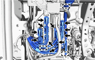
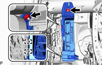
- Disconnect each connector.
- Disengage the 3 clamps.
- Disengage the 2 claws and pull down the 2 lock levers to disconnect the 2 connectors as shown in the illustration.

Remove in this Direction - Using a screwdriver, disengage the claw as shown in the illustration.
Remove in this Direction - Using a screwdriver, disengage the claw as shown in the illustration.
Remove in this Direction - Disengage the 2 guides.
- Remove the 2 nuts.
- Pull out the instrument panel junction block assembly with main body ECU.
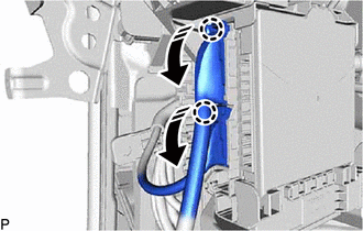
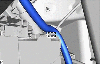
- Disengage the clamp.
- Disengage the clamp.
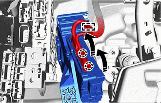
Remove in this Direction - Disengage the 2 claws and raise the 2 lock levers to disconnect the 2 connectors as shown in the illustration and remove the instrument panel junction block assembly with main body ECU.
- Disconnect each connector.
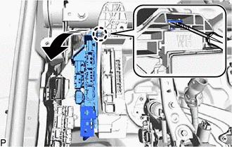
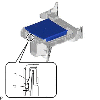
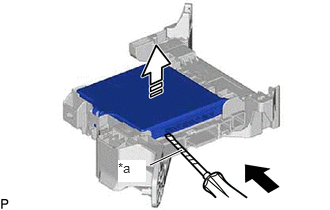
- REMOVE MAIN BODY ECU (MULTIPLEX NETWORK BODY ECU)
- Press the claw of the instrument panel junction block assembly as shown in the illustration to release the lock.
*1 Instrument Panel Junction Block Assembly *2 Main Body ECU (Multiplex Network Body ECU) 
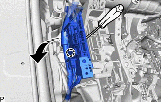
Push in this Direction - With the instrument panel junction block assembly lock released, insert a screwdriver with its tip wrapped with protective tape horizontally between the main body ECU (multiplex network body ECU) and instrument panel junction block assembly.
*a Protective Tape Insert in this Direction 
Remove in this Direction NOTE:- Use a screwdriver with a diameter between 5.0 mm (0.197 in.) and 6.3 mm (0.248 in.) and a length of approximately 90 mm (3.54 in.).
- Do not insert the screwdriver under the connector socket of the main body ECU (multiplex network body ECU).
- Using the screwdriver, carefully raise the main body ECU (multiplex network body ECU) to the position where the connector becomes disconnected.NOTE:
Do not twist the screwdriver to raise the main body ECU (multiplex network body ECU).
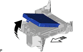
- Raise the main body ECU (multiplex network body ECU) as shown by the arrow (1), and then pull it out as shown by the arrow (2) in the illustration.
Remove in this Direction (1) Remove in this Direction (2) NOTE:Do not touch the main body ECU (multiplex network body ECU) connector.
- Press the claw of the instrument panel junction block assembly as shown in the illustration to release the lock.