Power Mirror Surface Position is not Memorized [12/2019 - 11/2023]: Procedure
- READ VALUE USING GTS
- Read the Data List according to the display on the GTS.
Body Electrical > Mirror L > Data List
Tester Display Measurement Item Range Normal Condition Diagnostic Note Seat Memory Switch1 Seat memory switch M1 switch signal OFF or ON OFF: Seat memory switch M1 switch off
ON: Seat memory switch M1 switch on- Seat Memory Switch2 Seat memory switch M2 switch signal OFF or ON OFF: Seat memory switch M2 switch off
ON: Seat memory switch M2 switch on- Seat Memory Set SW Seat memory switch SET switch signal OFF or ON OFF: Seat memory switch SET switch off
ON: Seat memory switch SET switch on- Body Electrical > Mirror L > Data List
Tester Display Seat Memory Switch1 Seat Memory Switch2 Seat Memory Set SW Body Electrical > Mirror R > Data List
Tester Display Measurement Item Range Normal Condition Diagnostic Note Seat Memory Switch1 Seat memory switch M1 switch signal OFF or ON OFF: Seat memory switch M1 switch off
ON: Seat memory switch M1 switch on- Seat Memory Switch2 Seat memory switch M2 switch signal OFF or ON OFF: Seat memory switch M2 switch off
ON: Seat memory switch M2 switch on- Seat Memory Set SW Seat memory switch SET switch signal OFF or ON OFF: Seat memory switch SET switch off
ON: Seat memory switch SET switch on- Body Electrical > Mirror R > Data List
Tester Display Seat Memory Switch1 Seat Memory Switch2 Seat Memory Set SW OK
On the GTS screen, ON or OFF is displayed accordingly.
Result
Proceed to OK NG
Result:
NG
See step 10
Result:
OK
See step 2
- Read the Data List according to the display on the GTS.
- CHECK SEAT MEMORY SWITCH (SEAT POSITION MEMORY FUNCTION)
- When any seat memory switch (M1 or M2) is pressed, check that the driver seat moves to the memorized position.
Refer to OPERATION CHECK [12/2019 - 10/2022] , or refer to OPERATION CHECK [10/2022 - 11/2023]
OK
The driver seat moves to the memorized position.
Result
Proceed to OK NG
Result:
NG
GO TO FRONT POWER SEAT CONTROL SYSTEM (Power Seat does not Return to Memorized Position)
Refer to Power Seat does not Return to Memorized Position [12/2019 - 10/2022] , or refer to Power Seat does not Return to Memorized Position [10/2022 - 11/2023]
Result:
OK
See step 3
- When any seat memory switch (M1 or M2) is pressed, check that the driver seat moves to the memorized position.
- CHECK MEMORY AND REACTIVATION FUNCTION
- Turn the ignition switch to ON.
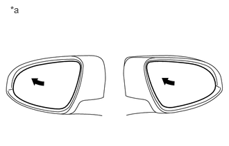
*a Turn to Fully Left Position - Using the outer mirror switch assembly, turn the mirror surface to the fully left position.
- Press the M1 switch while the SET switch is being pressed.
- Check that the buzzer sounds for 0.5 seconds and the mirror surface position is memorized.
- Using the outer mirror switch assembly, turn the mirror surface to the fully right position.
- Press the M1 switch.
- Check that the buzzer sounds for 0.1 seconds and the outer mirror automatically moves to the memorized fully left position.
Result
Result Proceed to Memory and reactivation functions on both mirrors are not normal A Memory and reactivation functions on driver door mirror are not normal B Memory and reactivation functions on front passenger door mirror are not normal C
Result:
A
REPLACE MAIN BODY ECU (MULTIPLEX NETWORK BODY ECU)
Refer to REMOVAL [12/2019 - 10/2022] , or refer to REMOVAL [10/2022 - 11/2023]
Result:
C
See step 7
Result:
B
See step 4
- Turn the ignition switch to ON.
- INSPECT OUTER REAR VIEW MIRROR ASSEMBLY (DRIVER DOOR) (WIRE HARNESS)
- Remove the outer mirror actuator assembly (driver door).
Refer to REMOVAL [12/2019 - 11/2023]
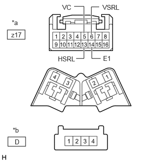
- Disconnect the z17 outer mirror control ECU assembly (driver door) connector.
- Measure the resistance according to the value(s) in the table below.
*a Front view of wire harness connector (to Outer Mirror Control ECU Assembly (Driver Door)) *b Front view of wire harness connector (to Outer Mirror Actuator Assembly (Driver Door)) STANDARD RESISTANCE:Tester Connection Condition Specified Condition z17-6 (VSRL) - D-2 Always Below 1 Ω z17-6 (VSRL) or D-2 - Body ground Always 10 kΩ or higher z17-5 (VC) - D-3 Always Below 1 Ω z17-5 (VC) or D-3 - Body ground Always 10 kΩ or higher z17-13 (HSRL) - D-1 Always Below 1 Ω z17-13 (HSRL) or D-1 - Body ground Always 10 kΩ or higher z17-14 (E1) - D-4 Always Below 1 Ω z17-14 (E1) - D-4 Always 10 kΩ or higher Result
Proceed to OK NG
Result:
NG
REPLACE OUTER REAR VIEW MIRROR ASSEMBLY (DRIVER DOOR)
Refer to REMOVAL [12/2019 - 11/2023]
Result:
OK
See step 5
- Remove the outer mirror actuator assembly (driver door).
- REPLACE OUTER MIRROR ACTUATOR ASSEMBLY (DRIVER DOOR)
- Temporarily replace the outer mirror actuator assembly (driver door) with a new or known good one.
Refer to REMOVAL [12/2019 - 11/2023]
Result
Proceed to NEXT
Result:
NEXT
See step 6
- Temporarily replace the outer mirror actuator assembly (driver door) with a new or known good one.
- CHECK MEMORY AND REACTIVATION FUNCTION
- Turn the ignition switch to ON.
*a Turn to Fully Left Position - Using the outer mirror switch assembly, turn the mirror surface to the fully left position.
- Press the M1 switch while the SET switch is being pressed.
- Check that the buzzer sounds for 0.5 seconds and the mirror surface position is memorized.
- Using the outer mirror switch assembly, turn the mirror surface to the fully right position.
- Press the M1 switch.
- Check that the buzzer sounds for 0.1 seconds and the outer mirror automatically moves to the memorized fully left position.
Result
Proceed to OK NG
Result:
OK
END (OUTER MIRROR ACTUATOR ASSEMBLY (DRIVER DOOR) WAS DEFECTIVE)
Result:
NG
REPLACE OUTER MIRROR CONTROL ECU ASSEMBLY (DRIVER DOOR)
Refer to REMOVAL [12/2019 - ]
- Turn the ignition switch to ON.
- INSPECT OUTER REAR VIEW MIRROR ASSEMBLY (FRONT PASSENGER DOOR) (WIRE HARNESS)
- Remove the outer mirror actuator assembly (front passenger door).
Refer to REMOVAL [12/2019 - 11/2023]
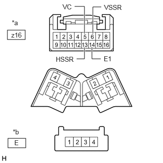
- Disconnect the z16 outer mirror control ECU assembly (front passenger door) connector.
- Measure the resistance according to the value(s) in the table below.
*a Front view of wire harness connector (to Outer Mirror Control ECU Assembly (Front Passenger Door)) *b Front view of wire harness connector (to Outer Mirror Actuator Assembly (Front Passenger Door)) STANDARD RESISTANCE:Tester Connection Condition Specified Condition z16-6 (VSSR) - E-2 Always Below 1 Ω z16-6 (VSSR) or E-2 - Body ground Always 10 kΩ or higher z16-5 (VC) - E-3 Always Below 1 Ω z16-5 (VC) or E-3 - Body ground Always 10 kΩ or higher z16-13 (HSSR) - E-1 Always Below 1 Ω z16-13 (HSSR) or E-1 - Body ground Always 10 kΩ or higher z16-14 (E1) - E-4 Always Below 1 Ω z16-14 (E1) or D-4 - Body ground Always 10 kΩ or higher Result
Proceed to OK NG
Result:
NG
REPLACE OUTER REAR VIEW MIRROR ASSEMBLY (FRONT PASSENGER DOOR)
Refer to REMOVAL [12/2019 - 11/2023]
Result:
OK
See step 8
- Remove the outer mirror actuator assembly (front passenger door).
- REPLACE OUTER MIRROR ACTUATOR ASSEMBLY (FRONT PASSENGER DOOR)
- Temporarily replace the outer mirror actuator assembly (front passenger door) with a new or known good one.
Refer to REMOVAL [12/2019 - 11/2023]
Result
Proceed to NEXT
Result:
NEXT
See step 9
- Temporarily replace the outer mirror actuator assembly (front passenger door) with a new or known good one.
- CHECK MEMORY AND REACTIVATION FUNCTION
- Turn the ignition switch to ON.
*a Turn to Fully Left Position - Using the outer mirror switch assembly, turn the mirror surface to the fully left position.
- Press the M1 switch while the SET switch is being pressed.
- Check that the buzzer sounds for 0.5 seconds and the mirror surface position is memorized.
- Using the outer mirror switch assembly, turn the mirror surface to the fully right position.
- Press the M1 switch.
- Check that the buzzer sounds for 0.1 seconds and the outer mirror automatically moves to the memorized fully left position.
Result
Proceed to OK NG
Result:
OK
END (OUTER MIRROR ACTUATOR ASSEMBLY (FRONT PASSENGER DOOR) WAS DEFECTIVE)
Result:
NG
REPLACE OUTER MIRROR CONTROL ECU ASSEMBLY (FRONT PASSENGER DOOR)
Refer to REMOVAL [12/2019 - ]
- Turn the ignition switch to ON.
- INSPECT SEAT MEMORY SWITCH
Refer to INSPECTION [12/2019 - ]
Result
Proceed to OK NG Result:
NG
REPLACE SEAT MEMORY SWITCH
Refer to REMOVAL [12/2019 - ]
Result:
OK
See step 11
- CHECK HARNESS AND CONNECTOR (SEAT MEMORY SWITCH - OUTER MIRROR CONTROL ECU ASSEMBLY (DRIVER DOOR) AND BODY GROUND)
- Disconnect the J23 outer mirror control ECU assembly (driver door) connector.
- Measure the resistance according to the value(s) in the table below.
Standard Resistance
Tester Connection Condition Specified Condition J21-2 (MMRY) - J23-1 (MM) Always Below 1 Ω J21-3 (1) - J23-2 (M1) Always Below 1 Ω J21-4 (2) - J23-3 (M2) Always Below 1 Ω J21-1 (E) - Body ground Always Below 1 Ω J21-2 (MMRY) or J23-1 (MM) - Body ground Always 10 kΩ or higher J21-3 (1) or J23-2 (M1) - Body ground Always 10 kΩ or higher J21-4 (2) or J23-3 (M2) - Body ground Always 10 kΩ or higher Result
Proceed to OK NG
Result:
OK
REPLACE OUTER MIRROR CONTROL ECU ASSEMBLY (DRIVER DOOR)
Refer to REMOVAL [12/2019 - ]
Result:
NG
REPAIR OR REPLACE HARNESS OR CONNECTOR