Terminals Of Ecu [12/2019 - 11/2023]
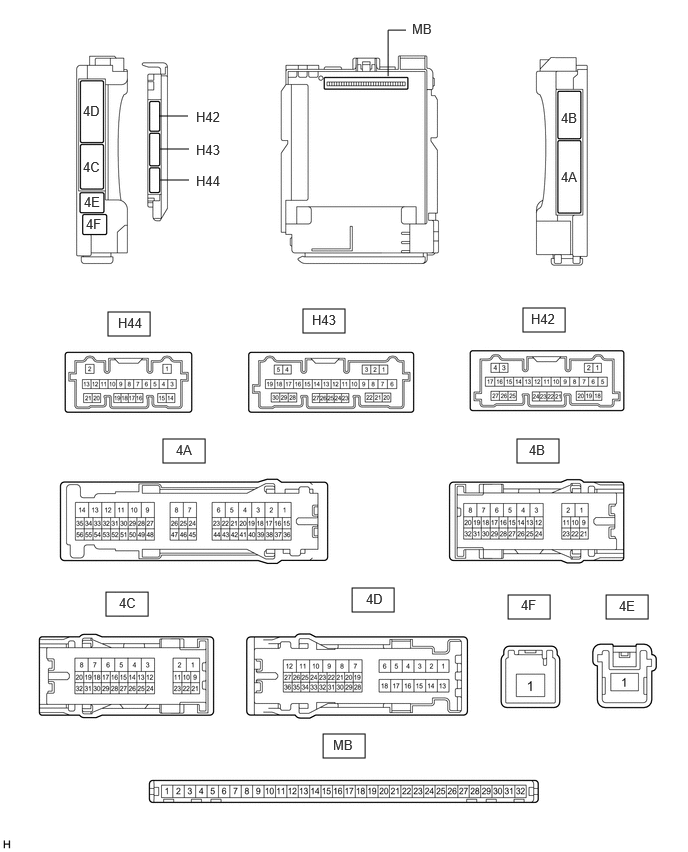
- CHECK INSTRUMENT PANEL JUNCTION BLOCK ASSEMBLY AND MAIN BODY ECU (MULTIPLEX NETWORK BODY ECU)
- Remove the main body ECU (multiplex network body ECU) from the instrument panel junction block assembly.
Refer to REMOVAL [12/2019 - 10/2022] , or refer to REMOVAL [10/2022 - 11/2023]
- Reconnect the instrument panel junction block assembly connectors.
- Measure the voltage and resistance according to the value(s) in the table below.
Terminal No. (Symbol) Terminal Description Condition Specified Condition MB-11 (GND1) - Body ground Ground Always Below 1 Ω H42-19 (GND2) - Body ground Ground Always Below 1 Ω MB-30 (ACC) - Body ground ACC power supply Ignition switch ACC 11 to 14 V Ignition switch off Below 1 V MB-31 (BECU) - Body ground Auxiliary battery power supply Ignition switch off*1
Always*211 to 14 V MB-32 (IG) - Body ground IG power supply Ignition switch ON 11 to 14 V Ignition switch off Below 1 V - *1: for HV Model
- *2: for Gasoline Model
- Install the main body ECU (multiplex network body ECU) to the instrument panel junction block assembly.
Refer to INSTALLATION [12/2019 - 10/2022] , or refer to INSTALLATION [10/2022 - 11/2023]
- Measure the voltage and check for pulses according to the value(s) in the table below.
Terminal No. (Symbol) Terminal Description Condition Specified Condition 4C-29 (BZR) - Body ground Wireless door lock buzzer output Active Test Wireless Buzzer is OFF Below 1 V Active Test Wireless Buzzer is ON Pulse generation
(frequency: 2 kHz, high voltage: 11 to 14 V, low voltage: below 1 V)
- Remove the main body ECU (multiplex network body ECU) from the instrument panel junction block assembly.
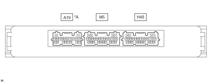
- CHECK CERTIFICATION ECU (SMART KEY ECU ASSEMBLY)
*A for Gasoline Model - - - Disconnect the H48 certification ECU (smart key ECU assembly) connector.
- Measure the voltage and resistance according to the value(s) in the table below.
Terminal No. (Symbol) Terminal Description Condition Specified Condition H48-4 (+B) - Body ground Auxiliary battery power supply Ignition switch off*1
Always*211 to 14 V H48-18 (E) - Body ground Ground Always Below 1 Ω - *1: for HV Model
- *2: for Gasoline Model
- Reconnect the H48 certification ECU (smart key ECU assembly) connector.
- Check for pulses according to the value(s) in the table below.
Terminal No. (Symbol) Terminal Description Condition Specified Condition M5-18 (RCO) - H48-18 (E) Output to electrical key and tire pressure warning ECU and receiver
(Power supply for electrical key and tire pressure warning ECU and receiver. Certification ECU (smart key ECU assembly) outputs 5 V when receiver starts operating.)Procedure: - Turn ignition switch off
- Bring electrical key transmitter sub-assembly outside detection area but within wireless function operational area
- Press lock or unlock switch of electrical key transmitter sub-assembly
Plus generation (See waveform 1) M5-19 (RDAM) - H48-18 (E) Electrical key and tire pressure warning ECU and receiver communication circuit Procedure: - Turn ignition switch off
- Lock all doors
- Bring electrical key transmitter sub-assembly outside detection area but within wireless function operational area
- Press lock or unlock switch of electrical key transmitter sub-assembly
Plus generation (See waveform 2) M5-20 (CSEL) - H48-18 (E) Communication channel switching circuit Procedure: - Turn ignition switch off
- Close all doors
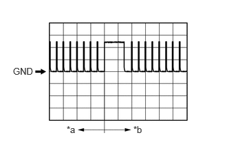
No pulse generation → Pulse generation - Using an oscilloscope, check waveform 1.
HINT:
The oscilloscope waveform shown in the illustration is an example for reference only. Noise, chattering, etc. are not shown.
*a Before lock or unlock switch of electrical key transmitter sub-assembly pressed *b After lock or unlock switch of electrical key transmitter sub-assembly pressed WAVEFORM 1 (REFERENCE)Item Content Tester connection M5-18 (RCO) - H48-18 (E) Tool setting 2 V/DIV., 500 ms/DIV. Condition Procedure: - Turn ignition switch off
- Bring electrical key transmitter sub-assembly outside detection area but within wireless function operational area
- Press lock or unlock switch of electrical key transmitter sub-assembly
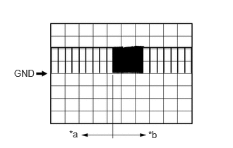
- Using an oscilloscope, check waveform 2.
HINT:
The oscilloscope waveform shown in the illustration is an example for reference only. Noise, chattering, etc. are not shown.
*a Before lock or unlock switch of electrical key transmitter sub-assembly pressed *b After lock or unlock switch of electrical key transmitter sub-assembly pressed WAVEFORM 2 (REFERENCE)Item Content Tester connection M5-19 (RDAM) - H48-18 (E) Tool setting 5 V/DIV., 500 ms/DIV. Condition Procedure: - Turn ignition switch off
- Lock all doors
- Bring electrical key transmitter sub-assembly outside detection area but within wireless function operational area
- Press lock or unlock switch of electrical key transmitter sub-assembly