Fuel Receiver Gauge Malfunction [11/2023 - ]: Procedure
- CHECK CAN COMMUNICATION SYSTEM
- Check if CAN communication DTCs are output.
For HV Model: Refer to DIAGNOSIS SYSTEM [11/2023 - ]
For Gasoline Model: Refer to DIAGNOSIS SYSTEM [11/2023 - ]
Result
Result Proceed to DTCs are not output A DTCs are output B
Result:
B
GO TO CAN COMMUNICATION SYSTEM
For HV Model: Refer to HOW TO PROCEED WITH TROUBLESHOOTING [11/2023 - ]
For Gasoline Model: Refer to HOW TO PROCEED WITH TROUBLESHOOTING [11/2023 - ]
Result:
A
See step 2
- Check if CAN communication DTCs are output.
- CHECK FOR DTC (ELECTRONICALLY CONTROLLED BRAKE SYSTEM)
- Check if electronically controlled brake system DTCs are output.
- For HV Model
Chassis > Brake/EPB > Trouble Codes
Chassis > Brake Booster > Trouble Codes
- For Gasoline Model
Chassis > Brake/EPB > Trouble Codes
Result
Result Proceed to DTCs are not output A DTCs are output B - For HV Model
Result:
B
GO TO ELECTRONICALLY CONTROLLED BRAKE SYSTEM
For HV Model: Refer to DIAGNOSTIC TROUBLE CODE CHART [11/2023 - ]
For Gasoline Model: Refer to DIAGNOSTIC TROUBLE CODE CHART [11/2023 - ]
Result:
A
See step 3
- Check if electronically controlled brake system DTCs are output.
- CHECK FOR DTC (SFI SYSTEM)
- Check if SFI system DTCs are output.
Powertrain > Engine > Trouble Codes
Result
Result Proceed to DTCs are not output A DTCs are output B
Result:
B
GO TO SFI SYSTEM
For HV Model: Refer to DIAGNOSTIC TROUBLE CODE CHART [11/2023 - 11/2024] , or refer to DIAGNOSTIC TROUBLE CODE CHART [11/2024 - ]
For Gasoline Model: Refer to DIAGNOSTIC TROUBLE CODE CHART [11/2023 - ]
Result:
A
See step 4
- Check if SFI system DTCs are output.
- CHECK SYMPTOMS
- Ask the customer about the problem symptoms.
Result
Result Proceed to Malfunction occurs when adding fuel (Even after adding fuel, reading does not increase at all or increases very slowly, etc.) A Malfunction occurs during normal driving (The reading does not change, decreases quickly or decreases when the vehicle is not being driven, etc.)
(The problem symptom recurs)B Malfunction occurs during normal driving (The reading does not change, decreases quickly or decreases when the vehicle is not being driven, etc.)
(The problem symptom does not recur)C
Result:
B
See step 8
Result:
C
See step 11
Result:
A
See step 5
- Ask the customer about the problem symptoms.
- PERFORM ACTIVE TEST USING GTS
- Perform the Active Test according to the display on the GTS.
Body Electrical > Combination Meter > Active Test
Tester Display Measurement Item Control Range Diagnostic Note Fuel Gauge Operation (Sender E) Fuel receiver gauge
(Fuel sender gauge lower limit)ON See [Display 1] Fuel Gauge Operation (Empty) Fuel receiver gauge
(Fuel receiver gauge indicates E)ON See [Display 1] Fuel Gauge Operation (Warning) Fuel receiver gauge
(Position at which fuel level warning light turns on/off)ON See [Display 1] Fuel Gauge Operation (1/4) Fuel receiver gauge
(Fuel receiver gauge indicates 1/4)ON See [Display 1] Fuel Gauge Operation (1/2) Fuel receiver gauge
(Fuel receiver gauge indicates 1/2)ON See [Display 1] Fuel Gauge Operation (3/4) Fuel receiver gauge
(Fuel receiver gauge indicates 3/4)ON See [Display 1] Fuel Gauge Operation (Full) Fuel receiver gauge
(Fuel receiver gauge indicates F)ON See [Display 1] Fuel Gauge Operation (Sender F) Fuel receiver gauge
(Fuel sender gauge upper limit)ON See [Display 1] [Display 1]: Fuel Gauge Operation
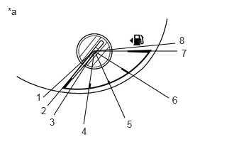
*a Fuel Receiver Gauge HINT:
Refer to the following table for the specified fuel receiver gauge position for each selected value:
Tester Display Fuel Receiver Gauge Indication Fuel Gauge Operation
(Sender E)Approximately 1 is indicated Fuel Gauge Operation
(Empty)Approximately 2 is indicated Fuel Gauge Operation
(Warning)Approximately 3 is indicated Fuel Gauge Operation
(1/4)Approximately 4 is indicated Fuel Gauge Operation
(1/2)Approximately 5 is indicated Fuel Gauge Operation
(3/4)Approximately 6 is indicated Fuel Gauge Operation
(Full)Approximately 7 is indicated Fuel Gauge Operation
(Sender F)Approximately 8 is indicated
Body Electrical > Combination Meter > Active Test
Tester Display Fuel Gauge Operation (Sender E) Body Electrical > Combination Meter > Active Test
Tester Display Fuel Gauge Operation (Empty) Body Electrical > Combination Meter > Active Test
Tester Display Fuel Gauge Operation (Warning) Body Electrical > Combination Meter > Active Test
Tester Display Fuel Gauge Operation (1/4) Body Electrical > Combination Meter > Active Test
Tester Display Fuel Gauge Operation (1/2) Body Electrical > Combination Meter > Active Test
Tester Display Fuel Gauge Operation (3/4) Body Electrical > Combination Meter > Active Test
Tester Display Fuel Gauge Operation (Full) Body Electrical > Combination Meter > Active Test
Tester Display Fuel Gauge Operation (Sender F) OK
Fuel receiver gauge indication is normal.
Result
Proceed to OK NG
Result:
NG
REPLACE COMBINATION METER ASSEMBLY
Refer to REMOVAL [12/2019 - ]
Result:
OK
See step 6
- Perform the Active Test according to the display on the GTS.
- INSPECT FUEL TANK SUB-ASSEMBLY
HINT:
Inspect the fuel tank sub-assembly and fuel sender assembly for deformation, foreign matter or an improperly installed fuel receiver gauge, as this may be the cause of the fuel receiver gauge malfunction.
- Visually check the fuel tank sub-assembly for any abnormalities.
- Check if there is an excessive amount of foreign matter in the fuel tank sub-assembly.
- Visually check the fuel sender gauge assembly for damage and confirm that it operates correctly.
- Check the installation condition of the fuel tank sub-assembly and fuel sender gauge assembly.
Result
Result Proceed to Normal A Appearance of the fuel tank sub-assembly is abnormal B There is an excessive amount of foreign matter in the fuel tank sub-assembly C The fuel sender gauge assembly is visually damaged or does not operate correctly D The fuel tank sub-assembly or fuel sender gauge assembly is not installed correctly E
Result:
B
REPLACE FUEL TANK SUB-ASSEMBLY
For HV Model: Refer to REMOVAL [11/2023 - ]
For Gasoline Model: Refer to REMOVAL [11/2023 - ]
Result:
C
CLEAN INSIDE OF FUEL TANK SUB-ASSEMBLY
Result:
D
REPLACE FUEL SENDER GAUGE ASSEMBLY
For HV Model: Refer to REMOVAL [11/2023 - ]
For Gasoline Model: Refer to REMOVAL [11/2023 - ]
Result:
E
INSTALL FUEL TANK SUB-ASSEMBLY OR FUEL SENDER GAUGE ASSEMBLY CORRECTLY
Result:
A
See step 7
- CHECK FUEL RECEIVER GAUGE (OPERATION BY ADDING FUEL)
- If the fuel tank sub-assembly is almost full, drain 20 liters (21.1 US qts, 17.6 Imp. qts) or more of fuel.
HINT:
This is not necessary when the fuel tank sub-assembly is sufficiently below full.
- Record the fuel receiver gauge reading.
- Turn the ignition switch off.
- Disconnect the cable from the negative (-) auxiliary battery terminal to reset the fuel receiver gauge.
- Connect the cable to the negative (-) auxiliary battery terminal.
- Turn the ignition switch to ON.
- Drive the vehicle at 1.8 km/h (1 mph) or more, then stop the vehicle.
- Turn the ignition switch off.
- Add the following amount of fuel or more.
- For HV Model: 7.0 liters (7.4 US qts, 6.2 Imp. qts)
- For Gasoline Model: 5.0 liters (5.3 US qts, 4.4 Imp. qts)
- Turn the ignition switch to ON.
- Check that the fuel receiver gauge reading increases in proportion to the amount of fuel added.
Result
Result Proceed to Fuel receiver gauge reading increases in proportion to the amount of fuel added A Fuel receiver gauge reading does not change even when fuel is added B
Result:
A
USE SIMULATION METHOD TO CHECK
Refer to HOW TO PROCEED WITH TROUBLESHOOTING [12/2019 - ]
Result:
B
REPLACE COMBINATION METER ASSEMBLY
Refer to REMOVAL [12/2019 - ]
- If the fuel tank sub-assembly is almost full, drain 20 liters (21.1 US qts, 17.6 Imp. qts) or more of fuel.
- PERFORM ACTIVE TEST USING GTS
- Perform the Active Test according to the display on the GTS.
Body Electrical > Combination Meter > Active Test
Tester Display Measurement Item Control Range Diagnostic Note Fuel Gauge Operation (Sender E) Fuel receiver gauge
(Fuel sender gauge lower limit)ON See [Display 1] Fuel Gauge Operation (Empty) Fuel receiver gauge
(Fuel receiver gauge indicates E)ON See [Display 1] Fuel Gauge Operation (Warning) Fuel receiver gauge
(Position at which fuel level warning light turns on/off)ON See [Display 1] Fuel Gauge Operation (1/4) Fuel receiver gauge
(Fuel receiver gauge indicates 1/4)ON See [Display 1] Fuel Gauge Operation (1/2) Fuel receiver gauge
(Fuel receiver gauge indicates 1/2)ON See [Display 1] Fuel Gauge Operation (3/4) Fuel receiver gauge
(Fuel receiver gauge indicates 3/4)ON See [Display 1] Fuel Gauge Operation (Full) Fuel receiver gauge
(Fuel receiver gauge indicates F)ON See [Display 1] Fuel Gauge Operation (Sender F) Fuel receiver gauge
(Fuel sender gauge upper limit)ON See [Display 1] [Display 1]: Fuel Gauge Operation
*a Fuel Receiver Gauge HINT:
Refer to the following table for the specified fuel receiver gauge position for each selected value:
Tester Display Fuel Receiver Gauge Indication Fuel Gauge Operation
(Sender E)Approximately 1 is indicated Fuel Gauge Operation
(Empty)Approximately 2 is indicated Fuel Gauge Operation
(Warning)Approximately 3 is indicated Fuel Gauge Operation
(1/4)Approximately 4 is indicated Fuel Gauge Operation
(1/2)Approximately 5 is indicated Fuel Gauge Operation
(3/4)Approximately 6 is indicated Fuel Gauge Operation
(Full)Approximately 7 is indicated Fuel Gauge Operation
(Sender F)Approximately 8 is indicated
Body Electrical > Combination Meter > Active Test
Tester Display Fuel Gauge Operation (Sender E) Body Electrical > Combination Meter > Active Test
Tester Display Fuel Gauge Operation (Empty) Body Electrical > Combination Meter > Active Test
Tester Display Fuel Gauge Operation (Warning) Body Electrical > Combination Meter > Active Test
Tester Display Fuel Gauge Operation (1/4) Body Electrical > Combination Meter > Active Test
Tester Display Fuel Gauge Operation (1/2) Body Electrical > Combination Meter > Active Test
Tester Display Fuel Gauge Operation (3/4) Body Electrical > Combination Meter > Active Test
Tester Display Fuel Gauge Operation (Full) Body Electrical > Combination Meter > Active Test
Tester Display Fuel Gauge Operation (Sender F) OK
Fuel receiver gauge indication is normal.
Result
Proceed to OK NG
Result:
NG
REPLACE COMBINATION METER ASSEMBLY
Refer to REMOVAL [12/2019 - ]
Result:
OK
See step 9
- Perform the Active Test according to the display on the GTS.
- INSPECT FUEL TANK SUB-ASSEMBLY
HINT:
Inspect the fuel tank sub-assembly and fuel sender assembly for deformation, foreign matter or an improperly installed fuel receiver gauge, as this may be the cause of the fuel receiver gauge malfunction.
- Visually check the fuel tank sub-assembly for any abnormalities.
- Check if there is an excessive amount of foreign matter in the fuel tank sub-assembly.
- Visually check the fuel sender gauge assembly for damage and confirm that it operates correctly.
- Check the installation condition of the fuel tank sub-assembly and fuel sender gauge assembly.
Result
Result Proceed to Normal A Appearance of the fuel tank sub-assembly is abnormal B There is an excessive amount of foreign matter in the fuel tank sub-assembly C The fuel sender gauge assembly is visually damaged or does not operate correctly D The fuel tank sub-assembly or fuel sender gauge assembly is not installed correctly E
Result:
B
REPLACE FUEL TANK SUB-ASSEMBLY
For HV Model: Refer to REMOVAL [11/2023 - ]
For Gasoline Model: Refer to REMOVAL [11/2023 - ]
Result:
C
CLEAN INSIDE OF FUEL TANK SUB-ASSEMBLY
Result:
D
REPLACE FUEL SENDER GAUGE ASSEMBLY
For HV Model: Refer to REMOVAL [11/2023 - ]
For Gasoline Model: Refer to REMOVAL [11/2023 - ]
Result:
E
INSTALL FUEL TANK SUB-ASSEMBLY OR FUEL SENDER GAUGE ASSEMBLY CORRECTLY
Result:
A
See step 10
- CHECK FUEL RECEIVER GAUGE
- Record the fuel receiver gauge reading.
- Turn the ignition switch off.
- Disconnect the cable from the negative (-) auxiliary battery terminal to reset the fuel receiver gauge.
- Connect the cable to the negative (-) auxiliary battery terminal.
- Turn the ignition switch to ON.
- Check if the fuel receiver gauge reading corresponds with the amount of fuel remaining in the fuel tank sub-assembly.
Result
Result Proceed to Fuel receiver gauge reading corresponds with the amount of fuel remaining in the fuel tank sub-assembly A Fuel receiver gauge reading does not correspond with the amount of fuel remaining in the fuel tank sub-assembly B
Result:
A
USE SIMULATION METHOD TO CHECK
Refer to HOW TO PROCEED WITH TROUBLESHOOTING [12/2019 - ]
Result:
B
REPLACE COMBINATION METER ASSEMBLY
Refer to REMOVAL [12/2019 - ]
- INSPECT FUEL TANK SUB-ASSEMBLY
HINT:
Inspect the fuel tank sub-assembly and fuel sender assembly for deformation, foreign matter or an improperly installed fuel receiver gauge, as this may be the cause of the fuel receiver gauge malfunction.
- Visually check the fuel tank sub-assembly for any abnormalities.
- Check if there is an excessive amount of foreign matter in the fuel tank sub-assembly.
- Visually check the fuel sender gauge assembly for damage and confirm that it operates correctly.
- Check the installation condition of the fuel tank sub-assembly and fuel sender gauge assembly.
Result
Result Proceed to Normal A Appearance of the fuel tank sub-assembly is abnormal B There is an excessive amount of foreign matter in the fuel tank sub-assembly C The fuel sender gauge assembly is visually damaged or does not operate correctly D The fuel tank sub-assembly or fuel sender gauge assembly is not installed correctly E
Result:
A
USE SIMULATION METHOD TO CHECK
Refer to HOW TO PROCEED WITH TROUBLESHOOTING [12/2019 - ]
Result:
B
REPLACE FUEL TANK SUB-ASSEMBLY
For HV Model: Refer to REMOVAL [11/2023 - ]
For Gasoline Model: Refer to REMOVAL [11/2023 - ]
Result:
C
CLEAN INSIDE OF FUEL TANK SUB-ASSEMBLY
Result:
D
REPLACE FUEL SENDER GAUGE ASSEMBLY
For HV Model: Refer to REMOVAL [11/2023 - ]
For Gasoline Model: Refer to REMOVAL [11/2023 - ]
Result:
E
INSTALL FUEL TANK SUB-ASSEMBLY OR FUEL SENDER GAUGE ASSEMBLY CORRECTLY