Steering Pad Switch Circuit [12/2019 - 10/2022]: Procedure
- INSPECT STEERING PAD SWITCH ASSEMBLY
- Remove the steering pad switch assembly.
Refer to REMOVAL [12/2019 - 10/2022]
- Inspect the steering pad switch assembly.
Refer to INSPECTION [12/2019 - ]
Result
Proceed to OK NG
Result:
NG
REPLACE STEERING PAD SWITCH ASSEMBLY. Refer to REMOVAL [12/2019 - 10/2022]
Result:
OK
See step 2
- Remove the steering pad switch assembly.
- INSPECT SPIRAL CABLE SUB-ASSEMBLY
- Remove the spiral cable sub-assembly.
Refer to REMOVAL [12/2019 - 10/2022]
- Inspect the spiral cable sub-assembly.
Refer to INSPECTION [12/2019 - ]
Result
Proceed to OK NG
Result:
NG
REPLACE SPIRAL CABLE SUB-ASSEMBLY. Refer to REMOVAL [12/2019 - 10/2022]
Result:
OK
See step 3
- Remove the spiral cable sub-assembly.
- CHECK COMBINATION METER ASSEMBLY (OUTPUT VOLTAGE)
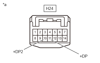
*a Front view of wire harness connector
(to Spiral Cable Sub-assembly)- Measure the voltage according to the value(s) in the table below.
Standard Voltage
Tester Connection Condition Specified Condition H24-10 (+DP2) - Body ground Ignition switch ON 4.8 to 5.2 V H24-11 (+DP) - Body ground Ignition switch ON 4.8 to 5.2 V Result
Proceed to OK NG
Result:
NG
See step 7
Result:
OK
See step 4
- Measure the voltage according to the value(s) in the table below.
- CONFIRM MODEL
- Choose the model to be inspected.
Result
Result Proceed to For 8 Inch Multi-display Type A For 12.3 Inch Multi-display Type B
Result:
B
See step 6
Result:
A
See step 5
- Choose the model to be inspected.
- CHECK HARNESS AND CONNECTOR (RADIO AND DISPLAY RECEIVER ASSEMBLY - SPIRAL CABLE SUB-ASSEMBLY AND BODY GROUND)
- Disconnect the H1 radio and display receiver assembly connector.
- Measure the resistance according to the value(s) in the table below.
Standard Resistance
Tester Connection Condition Specified Condition H1-24 (SWG) - H24-4 (EAU) Always Below 1 Ω H1-1 (GND1) - Body ground Always Below 1 Ω Result
Proceed to OK NG
Result:
OK
REPLACE RADIO AND DISPLAY RECEIVER ASSEMBLY. Refer to REMOVAL [12/2019 - 10/2022]
Result:
NG
REPAIR OR REPLACE HARNESS OR CONNECTOR
- CHECK HARNESS AND CONNECTOR (RADIO RECEIVER ASSEMBLY - SPIRAL CABLE SUB-ASSEMBLY AND BODY GROUND)
- Disconnect the H4 radio receiver assembly connector.
- Measure the resistance according to the value(s) in the table below.
Standard Resistance
Tester Connection Condition Specified Condition H4-24 (SWG) - H24-4 (EAU) Always Below 1 Ω H4-1 (GND1) - Body ground Always Below 1 Ω Result
Proceed to OK NG
Result:
OK
REPLACE RADIO RECEIVER ASSEMBLY. Refer to REMOVAL [12/2019 - 10/2022]
Result:
NG
REPAIR OR REPLACE HARNESS OR CONNECTOR
- CHECK HARNESS AND CONNECTOR (SPIRAL CABLE SUB-ASSEMBLY - COMBINATION METER ASSEMBLY)
- Disconnect the H21 combination meter assembly connector.
- Measure the resistance according to the value(s) in the table below.
Standard Resistance
Tester Connection Condition Specified Condition H24-10 (+DP2) - H21-28 (MSM+) Always Below 1 Ω H24-11 (+DP) - H21-29 (MSTI) Always Below 1 Ω H24-10 (+DP2) or H21-28 (MSM+) - Body ground Always 10 kΩ or higher H24-11 (+DP) or H21-29 (MSTI) - Body ground Always 10 kΩ or higher Result
Proceed to OK NG
Result:
OK
REPLACE COMBINATION METER ASSEMBLY. Refer to REMOVAL [12/2019 - ]
Result:
NG
REPAIR OR REPLACE HARNESS OR CONNECTOR