Speed Signal Circuit [12/2019 - 10/2022]: Procedure
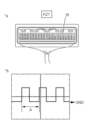
- INSPECT COMBINATION METER ASSEMBLY (INPUT WAVEFORM)
*a Component with harness connected
(Combination Meter Assembly)*b Waveform - Check the signal waveform according to the condition(s) in the table below.
Item Condition Tester connection H21-5 (SI) - Body ground Tool setting 5 V/DIV., 20 ms./DIV. Condition Ignition switch ON, wheel being rotated HINT:
When the system is functioning normally, one wheel revolution generates 4 pulses. As the vehicle speed increases, the width indicated by (A) in the illustration narrows.
Result
Result Proceed to The measured waveform is similar to that in the illustration A The measured waveform is not similar to that in the illustration
(Stuck low)B The measured waveform is not similar to that in the illustration
(Stuck high)C
Result:
B
See step 6
Result:
C
See step 11
Result:
A
See step 2
- Check the signal waveform according to the condition(s) in the table below.
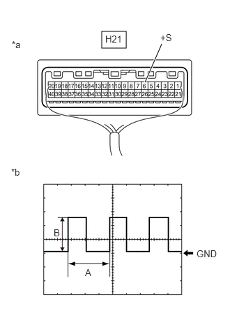
- INSPECT COMBINATION METER ASSEMBLY (OUTPUT WAVEFORM)
*a Component with harness connected
(Combination Meter Assembly)*b Waveform - Check the signal waveform according to the condition(s) in the table below.
Item Condition Tester connection H21-6 (+S) - Body ground Tool setting 5 V/DIV., 20 ms./DIV. Condition Ignition switch ON, wheel being rotated HINT:
- When the system is functioning normally, one wheel revolution generates 4 pulses. As the vehicle speed increases, the width indicated by (A) in the illustration narrows.
- The waveform (B) changes depending on the connected ECUs.
Result
Result Proceed to The measured waveform is similar to that in the illustration A The measured waveform is not similar to that in the illustration
(Stuck low)B The measured waveform is not similar to that in the illustration
(Stuck high)C
Result:
B
See step 4
Result:
C
REPLACE COMBINATION METER ASSEMBLY. Refer to REMOVAL [12/2019 - ]
Result:
A
See step 3
- Check the signal waveform according to the condition(s) in the table below.
- CHECK HARNESS AND CONNECTOR (EACH ECU - COMBINATION METER ASSEMBLY)
- Disconnect the A28 ECM connector.*1
- Disconnect the H48 certification ECU (smart key ECU assembly) connector.
- Disconnect the H1 radio and display receiver assembly connector.*2
- Disconnect the H4 radio receiver assembly connector.*3
- Disconnect the H18 navigation ECU connector.*4
- Disconnect the M37*3 or M38*2 stereo component amplifier assembly connector.*5
- Disconnect the H21 combination meter assembly connector.
- Measure the resistance according to the value(s) in the table below.
Standard Resistance
Tester Connection Condition Specified Condition A28-39 (SPD) - H21-6 (+S)*1 Always Below 1 Ω H48-19 (SPD) - H21-6 (+S) Always Below 1 Ω H1-27 (SPD) - H21-6 (+S)*2 Always Below 1 Ω H4-27 (SPD) - H21-6 (+S)*3 Always Below 1 Ω H18-9 (SPD) - H21-6 (+S)*4 Always Below 1 Ω M37-17 (SPD) - H21-6 (+S)*3, *5 Always Below 1 Ω M38-11 (SPD) - H21-6 (+S)*2, *5 Always Below 1 Ω - *1: for Gasoline Model
- *2: for 8 Inch Multi-display Type
- *3: for 12.3 Inch Multi-display Type
- *4: w/ Navigation System
- *5: for 11 Speakers
Result
Proceed to OK NG
Result:
OK
CHECK THE VOLTAGE AT TERMINAL SPD OF EACH ECU
Result:
NG
REPAIR OR REPLACE HARNESS OR CONNECTOR
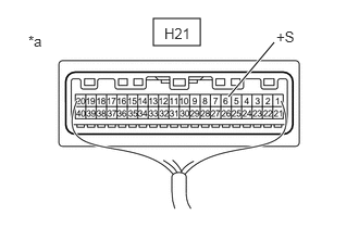
- INSPECT EACH ECU (INTERNAL SHORT)
*a Component with harness connected
(Combination Meter Assembly)- Disconnect one of the connectors below.NOTE:
After disconnecting a connector, perform all steps with all other ECUs connected.
Terminal No. (Symbol) ECU A28*1 ECM H48 Certification ECU (smart key ECU assembly) H1*2 Radio and display receiver assembly H4*3 Radio receiver assembly H18*4 Navigation ECU M37*3, *5 Stereo component amplifier assembly M38*2, *5 - *1: for Gasoline Model
- *2: for 8 Inch Multi-display Type
- *3: for 12.3 Inch Multi-display Type
- *4: w/ Navigation System
- *5: for 11 Speakers
- Measure the voltage according to the value(s) in the table below.NOTE:
Make sure to perform this inspection with the wheels stopped.
Standard Voltage
Tester Connection Condition Specified Condition H21-6(+S) - Body ground Ignition switch ON 5 to 14 V - Repeat steps (a) and (b) for each connected ECU.
HINT:
If the voltage changed to the specified voltage after disconnecting a connector, an internal short in the disconnected ECU is suspected.
Result
Result Proceed to After performing the inspection procedure for all connectors, the voltage did not change to the specified voltage A When disconnecting the connector of the ECM, the voltage changed to the specified voltage
(For Gasoline Model)B When disconnecting the connector of the certification ECU (smart key ECU assembly), the voltage changed to the specified voltage C When disconnecting the connector of the radio and display receiver assembly, the voltage changed to the specified voltage
(For 8 Inch Multi-display Type)D When disconnecting the connector of the radio receiver assembly, the voltage changed to the specified voltage
(For 12.3 Inch Multi-display Type)E When disconnecting the connector of the navigation ECU, the voltage changed to the specified voltage
(w/ Navigation System)F When disconnecting the connector of the stereo component amplifier assembly, the voltage changed to the specified voltage
(For 11 Speakers)G
Result:
B
REPLACE ECM. Refer to REMOVAL [12/2019 - 09/2020] , or refer to REMOVAL [09/2020 - 10/2022]
Result:
C
REPLACE CERTIFICATION ECU (SMART KEY ECU ASSEMBLY). Refer to REMOVAL [12/2019 - 11/2023]
Result:
D
REPLACE RADIO AND DISPLAY RECEIVER ASSEMBLY. Refer to REMOVAL [12/2019 - 10/2022]
Result:
E
REPLACE RADIO RECEIVER ASSEMBLY. Refer to REMOVAL [12/2019 - 10/2022]
Result:
F
REPLACE NAVIGATION ECU. Refer to REMOVAL [12/2019 - 10/2022]
Result:
G
REPLACE STEREO COMPONENT AMPLIFIER ASSEMBLY. Refer to REMOVAL [12/2019 - ]
Result:
A
See step 5
- Disconnect one of the connectors below.
- CHECK HARNESS AND CONNECTOR (EACH ECU - COMBINATION METER ASSEMBLY)
- Disconnect the A28 ECM connector.*1
- Disconnect the H48 certification ECU (smart key ECU assembly) connector.
- Disconnect the H1 radio and display receiver assembly connector.*2
- Disconnect the H4 radio receiver assembly connector.*3
- Disconnect the H18 navigation ECU connector.*4
- Disconnect the M37*3 or M38*2 stereo component amplifier assembly connector.*5
- Disconnect the H21 combination meter assembly connector.
- Measure the resistance according to the value(s) in the table below.
Standard Resistance
Tester Connection Condition Specified Condition A28-39 (SPD)*1, H48-19 (SPD), H1-27 (SPD)*2, H4-27 (SPD)*3, H18-9 (SPD)*4, M37-17 (SPD)*3, *5 or M38-11 (SPD)*2, *5 - H21-6 (+S) Always Below 1 Ω A28-39 (SPD)*1, H48-19 (SPD), H1-27 (SPD)*2, H4-27 (SPD)*3, H18-9 (SPD)*4, M37-17 (SPD)*3, *5, M38-11 (SPD)*2, *5 or H21-6 (+S) - Body ground Always 10 kΩ or higher - *1: for Gasoline Model
- *2: for 8 Inch Multi-display Type
- *3: for 12.3 Inch Multi-display Type
- *4: w/ Navigation System
- *5: for 11 Speakers
Result
Proceed to OK NG
Result:
OK
REPLACE COMBINATION METER ASSEMBLY. Refer to REMOVAL [12/2019 - ]
Result:
NG
REPAIR OR REPLACE HARNESS OR CONNECTOR
- CONFIRM MODEL
Result:
B
See step 9
Result:
A
See step 7
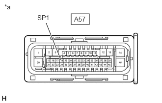
- INSPECT COMBINATION METER ASSEMBLY (OUTPUT VOLTAGE)
*a Front view of wire harness connector
(to No. 2 Skid Control ECU (Brake Actuator Assembly))- Disconnect the A57 No. 2 skid control ECU (brake actuator assembly) connector.
- Measure the voltage according to the value(s) in the table below.
Standard Voltage
Tester Connection Condition Specified Condition A57-18 (SP1) - Body ground Ignition switch ON 11 to 14 V Result
Proceed to OK NG
Result:
OK
REPLACE NO. 2 SKID CONTROL ECU (BRAKE ACTUATOR ASSEMBLY). Refer to REMOVAL [12/2019 - 10/2022]
Result:
NG
See step 8
- CHECK HARNESS AND CONNECTOR (NO. 2 SKID CONTROL ECU (BRAKE ACTUATOR ASSEMBLY) - COMBINATION METER ASSEMBLY)
- Disconnect the H21 combination meter assembly connector.
- Measure the resistance according to the value(s) in the table below.
Standard Resistance
Tester Connection Condition Specified Condition A57-18 (SP1) or H21-5 (SI) - Body ground Always 10 kΩ or higher Result
Proceed to OK NG
Result:
OK
REPLACE COMBINATION METER ASSEMBLY. Refer to REMOVAL [12/2019 - ]
Result:
NG
REPAIR OR REPLACE HARNESS OR CONNECTOR
- INSPECT COMBINATION METER ASSEMBLY (OUTPUT VOLTAGE)
*a Front view of wire harness connector
(to Skid Control ECU (Brake Actuator Assembly))- Disconnect the A39 skid control ECU (brake actuator assembly) connector.
- Measure the voltage according to the value(s) in the table below.
Standard Voltage
Tester Connection Condition Specified Condition A39-18 (SP1) - Body ground Ignition switch ON 11 to 14 V Result
Proceed to OK NG
Result:
OK
REPLACE SKID CONTROL ECU (BRAKE ACTUATOR ASSEMBLY). Refer to REMOVAL [12/2019 - 10/2022]
Result:
NG
See step 10
- CHECK HARNESS AND CONNECTOR (SKID CONTROL ECU (BRAKE ACTUATOR ASSEMBLY) - COMBINATION METER ASSEMBLY)
- Disconnect the H21 combination meter assembly connector.
- Measure the resistance according to the value(s) in the table below.
Standard Resistance
Tester Connection Condition Specified Condition A39-18 (SP1) or H21-5 (SI) - Body ground Always 10 kΩ or higher Result
Proceed to OK NG
Result:
OK
REPLACE COMBINATION METER ASSEMBLY. Refer to REMOVAL [12/2019 - ]
Result:
NG
REPAIR OR REPLACE HARNESS OR CONNECTOR
- CONFIRM MODEL
Result:
B
See step 13
Result:
A
See step 12
- CHECK HARNESS AND CONNECTOR (NO. 2 SKID CONTROL ECU (BRAKE ACTUATOR ASSEMBLY) - COMBINATION METER ASSEMBLY)
- Disconnect the A57 No. 2 skid control ECU (brake actuator assembly) connector.
- Disconnect the H21 combination meter assembly connector.
- Measure the resistance according to the value(s) in the table below.
Standard Resistance
Tester Connection Condition Specified Condition A57-18 (SP1) - H21-5 (SI) Always Below 1 Ω Result
Proceed to OK NG
Result:
OK
REPLACE NO. 2 SKID CONTROL ECU (BRAKE ACTUATOR ASSEMBLY). Refer to REMOVAL [12/2019 - 10/2022]
Result:
NG
REPAIR OR REPLACE HARNESS OR CONNECTOR
- CHECK HARNESS AND CONNECTOR (SKID CONTROL ECU (BRAKE ACTUATOR ASSEMBLY) - COMBINATION METER ASSEMBLY)
- Disconnect the A39 skid control ECU (brake actuator assembly) connector.
- Disconnect the H21 combination meter assembly connector.
- Measure the resistance according to the value(s) in the table below.
Standard Resistance
Tester Connection Condition Specified Condition A39-18 (SP1) - H21-5 (SI) Always Below 1 Ω Result
Proceed to OK NG
Result:
OK
REPLACE SKID CONTROL ECU (BRAKE ACTUATOR ASSEMBLY). Refer to REMOVAL [12/2019 - 10/2022]
Result:
NG
REPAIR OR REPLACE HARNESS OR CONNECTOR