Speed Signal Circuit [11/2023 - ]: Procedure
- INSPECT COMBINATION METER ASSEMBLY (INPUT WAVEFORM)
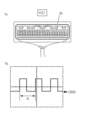
*a Component with harness connected
(Combination Meter Assembly)*b Waveform - Check the signal waveform according to the condition(s) in the table below.
Item Condition Tester connection H21-5 (SI) - Body ground Tool setting 5 V/DIV., 20 ms./DIV. Condition Ignition switch ON, wheel being rotated HINT:
When the system is functioning normally, one wheel revolution generates 4 pulses. As the vehicle speed increases, the width indicated by (A) in the illustration narrows.
Result
Result Proceed to The measured waveform is similar to that in the illustration A The measured waveform is not similar to that in the illustration
(Stuck low)B The measured waveform is not similar to that in the illustration
(Stuck high)C
Result:
B
See step 6
Result:
C
See step 9
Result:
A
See step 2
- Check the signal waveform according to the condition(s) in the table below.
- INSPECT COMBINATION METER ASSEMBLY (OUTPUT WAVEFORM)
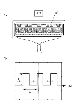
*a Component with harness connected
(Combination Meter Assembly)*b Waveform - Check the signal waveform according to the condition(s) in the table below.
Item Condition Tester connection H21-6 (+S) - Body ground Tool setting 5 V/DIV., 20 ms./DIV. Condition Ignition switch ON, wheel being rotated HINT:
- When the system is functioning normally, one wheel revolution generates 4 pulses. As the vehicle speed increases, the width indicated by (A) in the illustration narrows.
- The waveform (B) changes depending on the connected ECUs.
Result
Result Proceed to The measured waveform is similar to that in the illustration A The measured waveform is not similar to that in the illustration
(Stuck low)B The measured waveform is not similar to that in the illustration
(Stuck high)C
Result:
B
See step 4
Result:
C
REPLACE COMBINATION METER ASSEMBLY. Refer to REMOVAL [12/2019 - ]
Result:
A
See step 3
- Check the signal waveform according to the condition(s) in the table below.
- CHECK HARNESS AND CONNECTOR (EACH ECU - COMBINATION METER ASSEMBLY)
- Disconnect the H107 radio and display receiver assembly connector.
- Disconnect the M38 stereo component amplifier assembly connector.*
- Disconnect the H21 combination meter assembly connector.
- Measure the resistance according to the value(s) in the table below.
Standard Resistance
Tester Connection Condition Specified Condition H107-8 (SPD) - H21-6 (+S) Always Below 1 Ω M38-11 (SPD) - H21-6 (+S)* Always Below 1 Ω - *: w/ "JBL" Sound System
Result
Proceed to OK NG
Result:
OK
CHECK THE VOLTAGE AT TERMINAL SPD OF EACH ECU
Result:
NG
REPAIR OR REPLACE HARNESS OR CONNECTOR
- INSPECT EACH ECU (INTERNAL SHORT)
*a Component with harness connected
(Combination Meter Assembly)- Disconnect one of the connectors below.NOTE:
After disconnecting a connector, perform all steps with all other ECUs connected.
Terminal No. (Symbol) ECU H107 Radio and display receiver assembly M38* Stereo component amplifier assembly - *: w/ "JBL" Sound System
- Measure the voltage according to the value(s) in the table below.NOTE:
Make sure to perform this inspection with the wheels stopped.
Standard Voltage
Tester Connection Condition Specified Condition H21-6 (+S) - Body ground Ignition switch ON 5 to 14 V - Repeat steps (a) and (b) for each connected ECU.
HINT:
If the voltage changed to the specified voltage after disconnecting a connector, an internal short in the disconnected ECU is suspected.
Result
Result Proceed to After performing the inspection procedure for all connectors, the voltage did not change to the specified voltage A When disconnecting the connector of the radio and display receiver assembly, the voltage changed to the specified voltage B When disconnecting the connector of the stereo component amplifier assembly, the voltage changed to the specified voltage
(w/ "JBL" Sound System)C
Result:
B
REPLACE RADIO AND DISPLAY RECEIVER ASSEMBLY. Refer to REMOVAL [11/2023 - ]
Result:
C
REPLACE STEREO COMPONENT AMPLIFIER ASSEMBLY. Refer to REMOVAL [12/2019 - ]
Result:
A
See step 5
- Disconnect one of the connectors below.
- CHECK HARNESS AND CONNECTOR (EACH ECU - COMBINATION METER ASSEMBLY)
- Disconnect the H107 radio and display receiver assembly connector.
- Disconnect the M37 stereo component amplifier assembly connector.*
- Disconnect the H21 combination meter assembly connector.
- Measure the resistance according to the value(s) in the table below.
Standard Resistance
Tester Connection Condition Specified Condition H107-8 (SPD) or M38-11 (SPD)* - H21-6 (+S) Always Below 1 Ω H107-8 (SPD), M38-11 (SPD)* or H21-6 (+S) - Body ground Always 10 kΩ or higher - *: w/ "JBL" Sound System
Result
Proceed to OK NG
Result:
OK
REPLACE COMBINATION METER ASSEMBLY. Refer to REMOVAL [12/2019 - ]
Result:
NG
REPAIR OR REPLACE HARNESS OR CONNECTOR
- CHECK FOR DTC (SMART ACCESS SYSTEM WITH PUSH-BUTTON START (FOR START FUNCTION))
- Check if smart access system with push-button start (for start function) DTCs are output.
Body Electrical > Power Source Control > Trouble Codes
Result
Result Proceed to DTCs are not output A DTCs are output B
Result:
B
GO TO SMART ACCESS SYSTEM WITH PUSH-BUTTON START (FOR START FUNCTION)
For HV Model: Refer to DIAGNOSTIC TROUBLE CODE CHART [11/2023 - ]
For Gasoline Model: Refer to DIAGNOSTIC TROUBLE CODE CHART [11/2023 - ]
Result:
A
See step 7
- Check if smart access system with push-button start (for start function) DTCs are output.
- INSPECT COMBINATION METER ASSEMBLY
HINT:
This procedure is performed to check the diode inside the combination meter assembly.
- Remove the combination meter assembly.
Refer to REMOVAL [12/2019 - ]
- Measure the internal resistance of the combination meter assembly.
Standard Resistance
Tester Connection Tester Connection Condition Measured Value H21-39 (IG+) - H21-5 (SI) - Positive (+) tester probe → H21-39 (IG+)
- Negative (-) tester probe → H21-5 (SI)
Always A H21-39 (IG+) - H21-5 (SI) - Positive (+) tester probe → H21-5 (SI)
- Negative (-) tester probe → H21-39 (IG+)
Always B OK
There is a large difference between the measured value (A) and the measured value (B).
Result
Proceed to OK NG
Result:
NG
REPLACE COMBINATION METER ASSEMBLY. Refer to REMOVAL [12/2019 - ]
Result:
OK
See step 8
- Remove the combination meter assembly.
- CHECK HARNESS AND CONNECTOR (CERTIFICATION ECU (SMART KEY ECU ASSEMBLY) - COMBINATION METER ASSEMBLY)
- Disconnect the H138 certification ECU (smart key ECU assembly) connector.
- Disconnect the H21 combination meter assembly connector.
- Measure the resistance according to the value(s) in the table below.
Standard Resistance
Tester Connection Condition Specified Condition H138-28 (SPDO) or H21-5 (SI) - Body ground Always 10 kΩ or higher Result
Proceed to OK NG
Result:
OK
REPLACE CERTIFICATION ECU (SMART KEY ECU ASSEMBLY). Refer to REMOVAL [11/2023 - ]
Result:
NG
REPAIR OR REPLACE HARNESS OR CONNECTOR
- CHECK FOR DTC (SMART ACCESS SYSTEM WITH PUSH-BUTTON START (FOR START FUNCTION))
- Check if smart access system with push-button start (for start function) DTCs are output.
Body Electrical > Power Source Control > Trouble Codes
Result
Result Proceed to DTCs are not output A DTCs are output B
Result:
B
GO TO SMART ACCESS SYSTEM WITH PUSH-BUTTON START (FOR START FUNCTION)
For HV Model: Refer to DIAGNOSTIC TROUBLE CODE CHART [11/2023 - ]
For Gasoline Model: Refer to DIAGNOSTIC TROUBLE CODE CHART [11/2023 - ]
Result:
A
See step 10
- Check if smart access system with push-button start (for start function) DTCs are output.
- CHECK HARNESS AND CONNECTOR (CERTIFICATION ECU (SMART KEY ECU ASSEMBLY) - COMBINATION METER ASSEMBLY)
- Disconnect the H138 certification ECU (smart key ECU assembly) connector.
- Disconnect the H21 combination meter assembly connector.
- Measure the resistance according to the value(s) in the table below.
Standard Resistance
Tester Connection Condition Specified Condition H138-28 (SPDO) - H21-5 (SI) Always Below 1 Ω Result
Proceed to OK NG
Result:
OK
REPLACE CERTIFICATION ECU (SMART KEY ECU ASSEMBLY). Refer to REMOVAL [11/2023 - ]
Result:
NG
REPAIR OR REPLACE HARNESS OR CONNECTOR